

Electric damping shock absorber
A shock absorber and electric damping technology, which is applied in the direction of non-rotational vibration suppression, etc., can solve the problems of affecting the life of the vehicle, affecting the comfort of the vehicle, the life of the shock absorber and functional limitations, etc., and achieve good energy saving, vibration reduction, and good vibration reduction. shock effect
- Summary
- Abstract
- Description
- Claims
- Application Information
AI Technical Summary
Problems solved by technology
Method used
Image

Examples
Embodiment 1
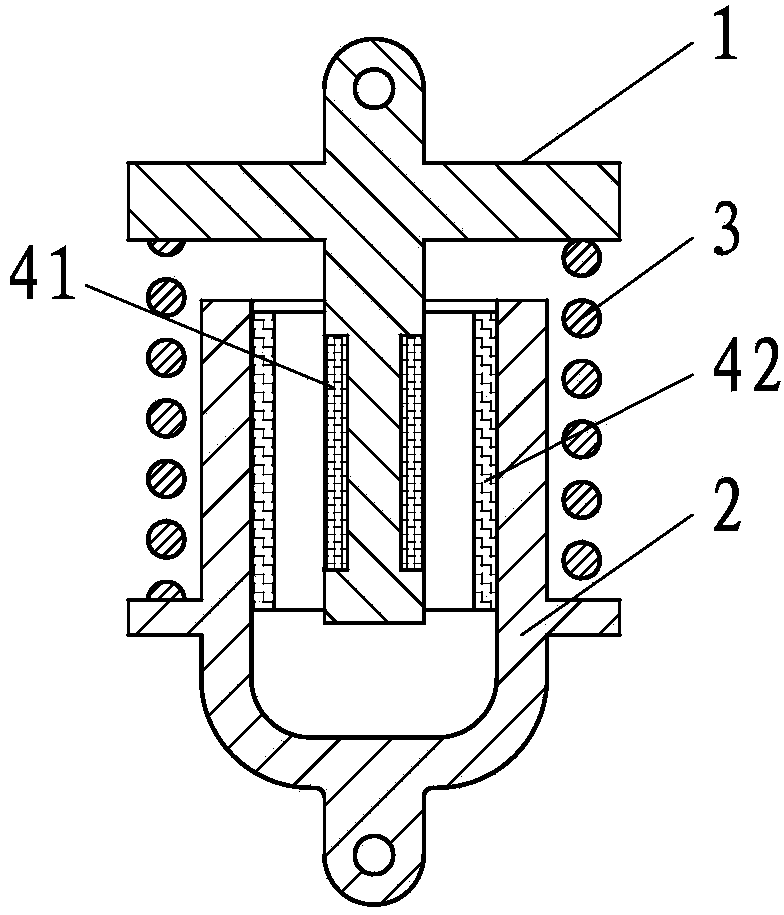
[0033] Such as figure 1 The shown electric damping shock absorber comprises a dynamic structural part 1, a static structural part 2 and an elastic element 3, and the elastic element 3 is arranged between the dynamic structural part 1 and the static structural part 2, and the linear electric mechanism The static electromagnetic part 42 is arranged on the static structural part 2, the electromagnetic moving part 41 of the linear electric mechanism is arranged on the moving structural part 1, and the electromagnetic static part 42 and the electromagnetic moving part 41 cooperate electromagnetically. .
[0034] In this embodiment, specifically, the electromagnetic static part 42 is set as an inductive closed coil, and the electromagnetic moving part 41 is set as a permanent magnet.
[0035] As an alternative embodiment, the electromagnetic static part 42 can also be changed to a permanent magnet, and the electromagnetic moving part 41 can be changed to an inductive closed coil. ...
Embodiment 2
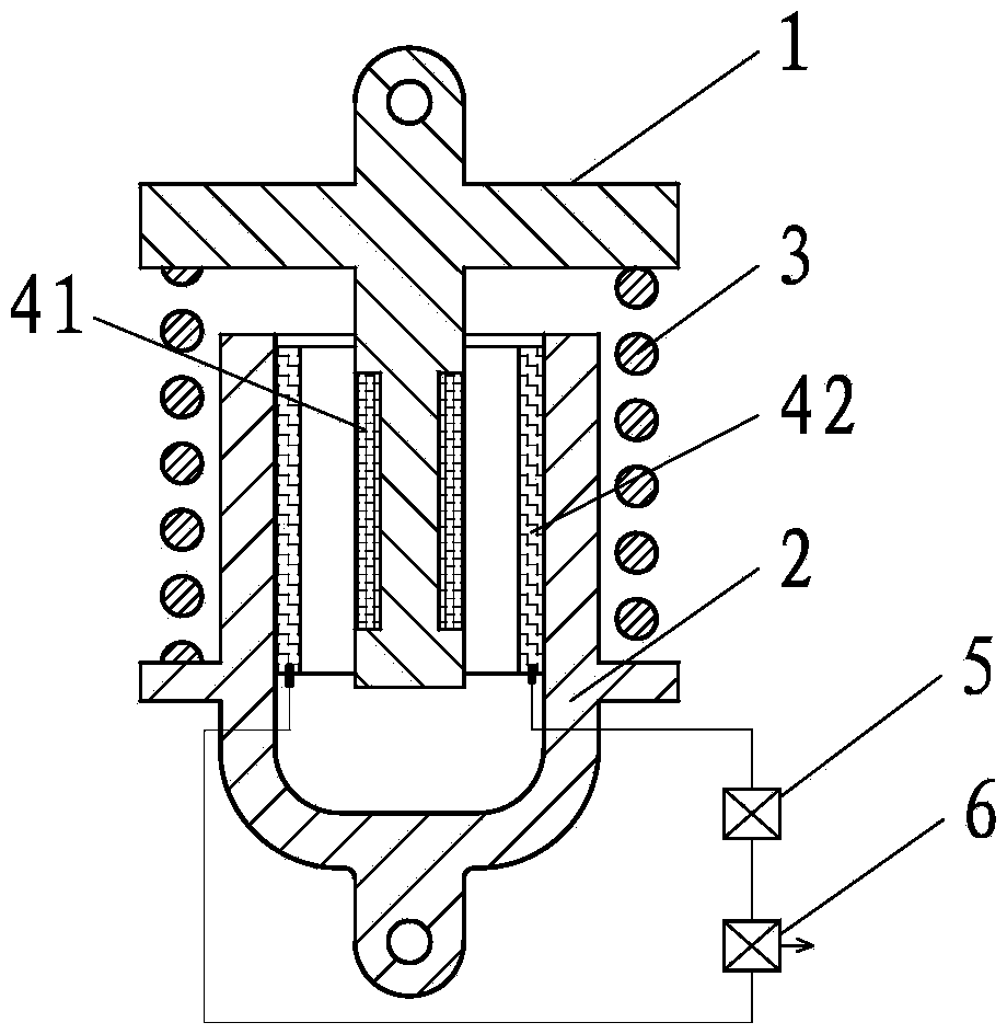
[0037] Such as figure 2 Shown electric damper, its difference with embodiment 1 is: change described electromagnetic static part 42 into inductance non-closed coil, change described electromagnetic moving part 41 into permanent magnet, described inductance The non-closed coil communicates with the load 6 via the control unit 5 .
[0038] As an alternative embodiment, the control unit 5 is eliminated, and the inductive non-closed coil is directly connected to the load 6 .
[0039] As a convertible embodiment, the electromagnetic static part 42 is changed to a permanent magnet, and the electromagnetic moving part 41 is changed to an inductive non-closed coil, and the inductive non-closed coil is communicated with the load 6 or via the control unit 5 communicates with load 6 .
Embodiment 3
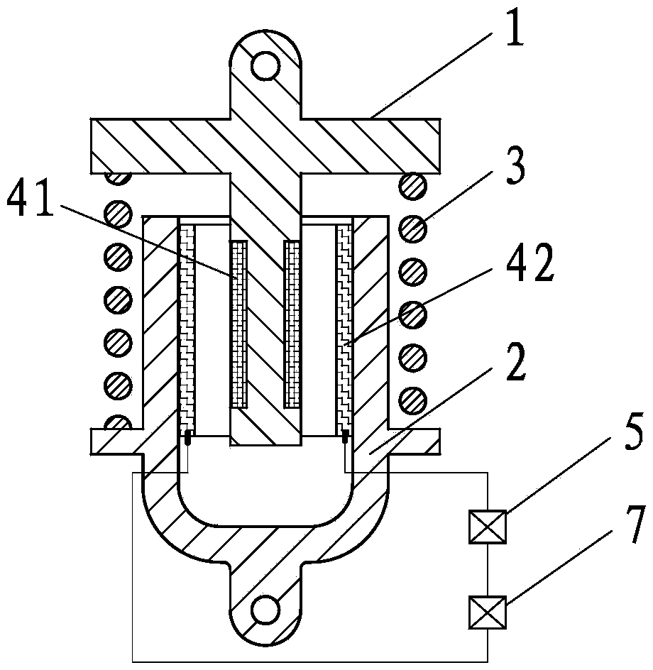
[0041] Such as image 3 The difference between the shown electric damping shock absorber and Embodiment 1 is that the electromagnetic static part 42 is changed to an inductance non-closed coil, the electromagnetic moving part 41 is set as an excitation magnet, and the inductance non-closed The coil communicates with the power source 7 via the control unit 5 .
[0042] As an alternative embodiment, the control unit 5 is eliminated, and the inductive non-closed coil is directly connected to the power supply 7 .
[0043] As a convertible embodiment, the electromagnetic static part 42 is changed to an excitation magnet, and the electromagnetic moving part 41 is changed to an inductive non-closed coil, and the inductive non-closed coil is communicated with the power supply 7 or via the control unit 5 Connect with power supply 7.
PUM
 Abstract
Description
Claims
Application Information