Medical image processing device and medical image processing method
A medical image and processing device technology, applied in image data processing, image analysis, image enhancement, etc., can solve the problems that it is not easy to obtain high-quality blood oxygen level-dependent functional magnetic resonance imaging, and has no correlation
- Summary
- Abstract
- Description
- Claims
- Application Information
AI Technical Summary
Problems solved by technology
Method used
Image
Examples
no. 1 approach
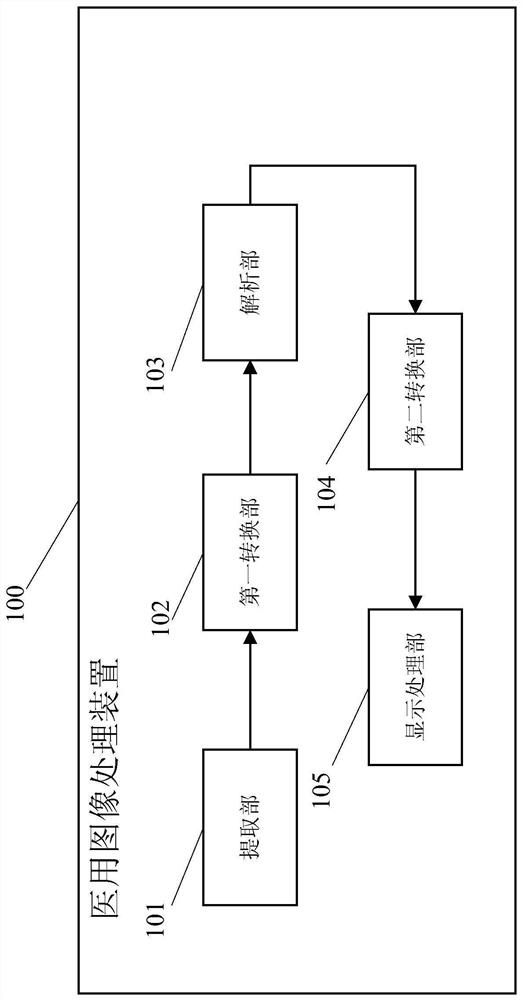
[0041] figure 1 It is a block diagram showing the configuration of the image processing device according to the first embodiment of the present invention.
[0042] Such as figure 1 As shown, the medical image processing device 100 includes an extraction unit 101 , a first conversion unit 102 , an analysis unit 103 , a second conversion unit 104 and a display processing unit 105 .
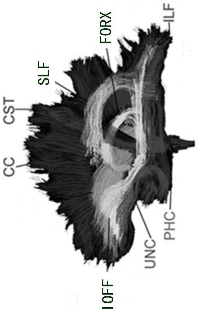
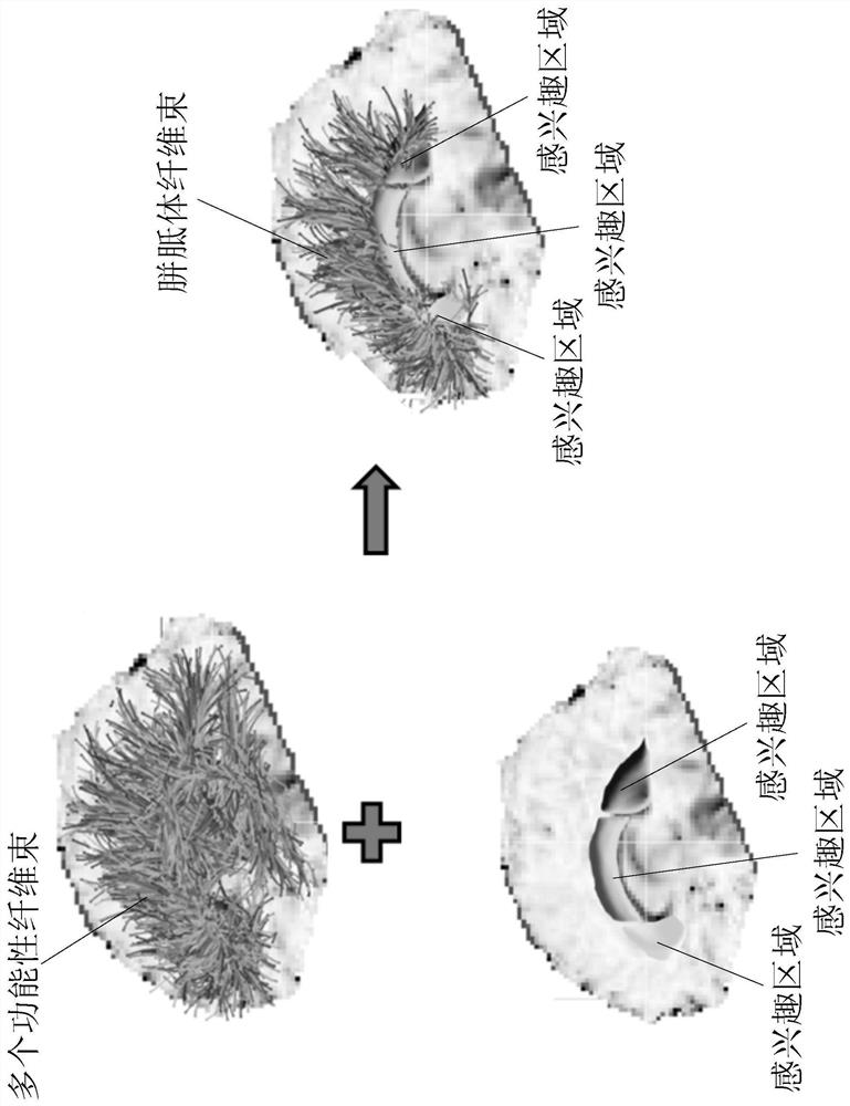
[0043] The extraction unit 101 extracts positional information of nerve distribution from the subject data. The subject data include fiber bundle images. The fiber bundle image is a nerve fiber image related to a nerve fiber bundle in the subject's brain. The fiber tract image is generated, for example, by applying a fiber tract tracking technique to a diffusion tensor image generated by imaging the subject's brain. Diffusion tensor imaging enables the assessment of the integrity of white matter fiber tracts by imaging the diffusion properties of water molecules. Current diffusion tensor imagin...
no. 2 approach
[0074] The second embodiment is a modified example of the first embodiment. The difference between the second embodiment and the first embodiment is that in the second embodiment, the medical image processing device 200 also processes the tumor image in the subject data, so as to determine the nerve fibers of the subject affected by the tumor. bundle and display it. In addition, in this embodiment, a tumor is described as an example of an affected part, but actually the affected part may be other conditions, such as trauma, blood clot, and the like.
[0075] The extraction unit 201, the first conversion unit 202, the analysis unit 203, the second conversion unit 204, and the display processing unit 205 in the medical image processing apparatus 200 of the second embodiment are the same as the extraction unit 101 and the first conversion unit 102 of the first embodiment. , the analysis unit 103 , and the second conversion unit 104 have additional functions compared to the displ...
no. 3 approach
[0102] After the region of interest is converted into object data by the second converting unit 204, fiber bundles that conform to the logical relationship of each region of interest cannot be found sometimes. For example, if Figure 10 As shown, in the case where the tumor region shifts the fiber bundle, the region of interest B converted into the subject data exists inside the tumor region E, and at this time, it can be observed that the fiber bundle X1 is shifted by the tumor region E , and did not pass through the fiber bundle of the region of interest B in the tumor region E. However, the functional fiber bundles need to be jointly determined according to the regions of interest A, B, and C, that is, the affected functional fiber bundles cannot be uniquely determined only according to the regions of interest A and C located outside the tumor region E .
[0103] The third embodiment is a modified example of the second embodiment. The medical image processing apparatus o...
PUM
 Abstract
Description
Claims
Application Information
 - R&D
- Intellectual Property
- Life Sciences
- Materials
- Tech Scout
- Unparalleled Data Quality
- Higher Quality Content
- 60% Fewer Hallucinations
Browse by: Latest US Patents, China's latest patents, Technical Efficacy Thesaurus, Application Domain, Technology Topic, Popular Technical Reports.
© 2025 PatSnap. All rights reserved.Legal|Privacy policy|Modern Slavery Act Transparency Statement|Sitemap|About US| Contact US: help@patsnap.com


