Supercharge Your Innovation With Domain-Expert AI Agents!

A modular multilevel converter and its sub-module structure

A modular multi-level, sub-module technology, applied in the direction of converting AC power input to DC power output, electrical components, output power conversion devices, etc., can solve poor fault tolerance, fast response time, increase system cost, etc. problems, achieve the effect of maintaining current stress balance, realizing independent protection, and improving operating efficiency

Active Publication Date: 2021-03-12
CHINA ELECTRIC POWER RES INST +2
View PDF4 Cites 0 Cited by
  • Summary
  • Abstract
  • Description
  • Claims
  • Application Information

AI Technical Summary

Problems solved by technology

However, the first processing method has long response time and complicated restart of AC equipment due to its mechanical limitations; the disadvantage of the second processing method is that the DC circuit breaker technology is not yet mature and the cost is high, so it is difficult to apply to actual projects; The first two methods, the third method has a fast response time and a strong ability to restore the system to normal operation after a fault, so it has become an effective solution to deal with short-circuit faults on the DC side of MMC-HVDC
The number of power semiconductor devices in the full-bridge sub-module is twice that of the half-bridge sub-module, which increases the system cost and reduces the operating efficiency of the converter; although the structure of the clamping twin sub-module is simple, it has poor fault tolerance. If the tube is damaged, the sub-module will not be able to achieve the normal output of the level, which will affect the normal operation of the entire system

Method used


Image

  • A modular multilevel converter and its sub-module structure
  • A modular multilevel converter and its sub-module structure
  • A modular multilevel converter and its sub-module structure

Examples


Embodiment Construction

[0042] The technical solution of the present invention will be described in further detail below in conjunction with the accompanying drawings.

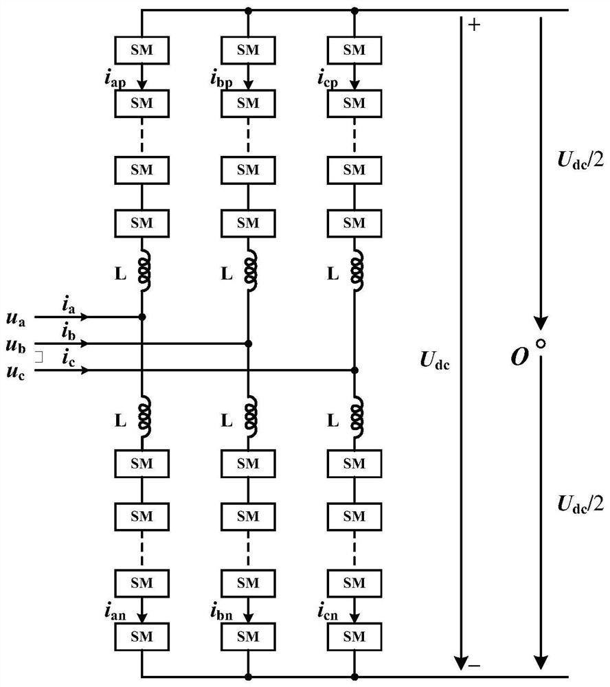
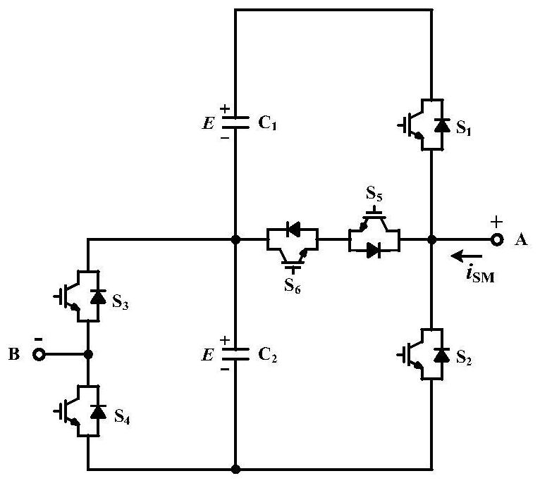
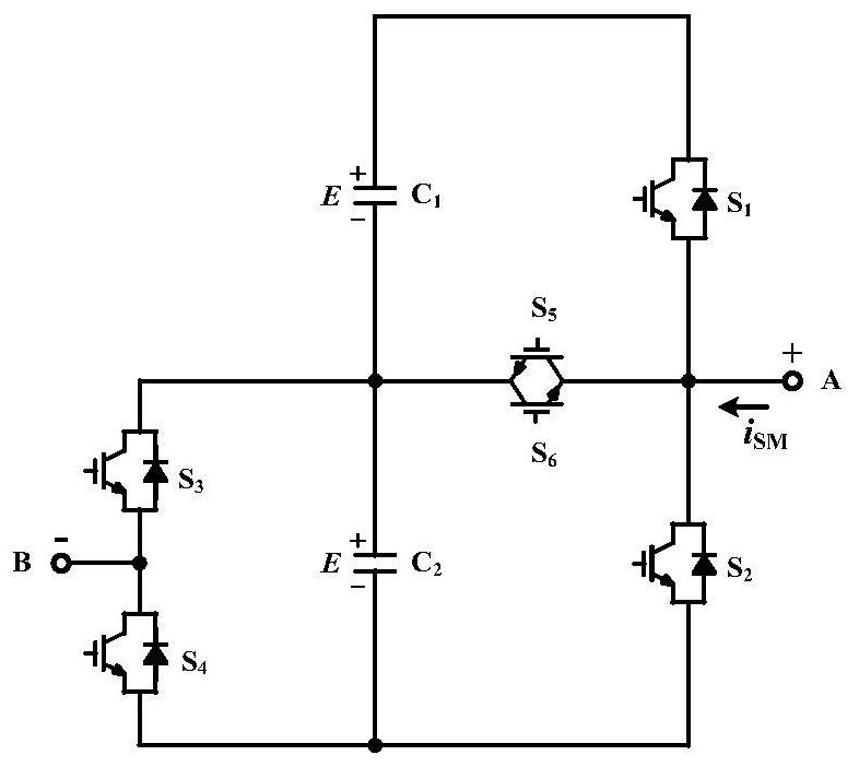
[0043] The invention discloses a modular multilevel converter sub-module structure with a fault ride-through function, which adjusts the current stress balance of two capacitors and eight power switch tubes in the sub-module through redundant switch states; In the mode, three levels can be output, which improves the level integration of the sub-module; in the blocking mode, all the capacitors of the sub-module are put into the bridge arm, and the capacitor of the sub-module is charged to generate a reverse electromotive force to isolate the DC side fault function. The sub-module structure of the present invention is applied in the MMC-HVDC system, which can realize the autonomous protection of DC faults, and due to the symmetry of the structure, the output characteristics of the sub-module structure in the blocking mode are symmetric...


PUM


Abstract

The present invention provides a modular multilevel converter and its sub-module structure, wherein: the multi-level converter includes: an inductor and a sub-module structure cascaded with each other, the inductor and the sub-module structure are connected in series to form a bridge arm, Two sets of bridge arms are connected in series to form a phase unit; the sub-module structure includes: positive terminal branch, negative terminal branch, capacitor branch and bidirectional power switch branch; the positive terminal branch and the capacitor branch are connected in parallel, and the bidirectional power switch branch The two ends are respectively connected to the midpoint of the positive extreme branch and the capacitor branch; one end of the negative extreme branch is connected to the parallel connection of the positive extreme branch and the capacitor branch, and the other end is connected to the midpoint of the capacitor branch. The technical solution provided by the present invention is applied in the MMC-HVDC system, which can realize the autonomous protection of DC faults, and due to the symmetry of the structure, the output characteristics of the sub-module structure are symmetrical with respect to the current direction in the blocking mode, and the symmetry is good The stability is conducive to maintaining the current stress balance of the power devices and capacitors in the sub-module.

Description

technical field [0001] The invention relates to the technical field of flexible DC power transmission and distribution, in particular to a modular multilevel converter and its sub-module structure. Background technique [0002] Since the advent of Modular Multilevel Converter (MMC) in 2002, it has increasingly become a high-voltage DC (High It is one of the most promising converter topologies in Voltage Direct Current (HVDC) transmission system. Most of the MMC-HVDC projects put into operation currently use the Half Bridge Sub-Module (HBSM) structure, which has a small number of power devices, low system cost, and high operating efficiency. However, when the DC side fails, the converter It does not have active protection capability by itself, and needs to use AC relay protection equipment to isolate faults. [0003] DC side short-circuit fault is a common fault in DC transmission, especially in overhead lines. At present, there are three main ways to deal with DC side fau...

Claims


Application Information

Patent Timeline
Patent Type & Authority Patents(China)
IPC IPC(8): H02M7/483
CPCH02M7/483H02M7/4835
Inventor 迟永宁李琰李武华孙蔚杨贺雅董玉斐
Owner CHINA ELECTRIC POWER RES INST
Features
  • R&D
  • Intellectual Property
  • Life Sciences
  • Materials
  • Tech Scout
  • Unparalleled Data Quality
  • Higher Quality Content
  • 60% Fewer Hallucinations
Learn More