
Roller lever operating device and roller lever valve equipped therewith

A lever manipulation, lever valve technology, applied in mechanical equipment, valve operation/release device, valve details, etc., can solve the problems of roller lever damage, high bending load of roller lever, etc., to reduce internal stress, large spring length, The effect of compact size

Active Publication Date: 2019-12-31
FESTO AG & CO KG
View PDF6 Cites 0 Cited by
  • Summary
  • Abstract
  • Description
  • Claims
  • Application Information

AI Technical Summary

Problems solved by technology

Since the stop pin protrudes laterally away from the roller lever, it is subjected to high bending loads when it hits the counter-stop surface, so that the roller lever can be damaged

Method used


Image

  • Roller lever operating device and roller lever valve equipped therewith
  • Roller lever operating device and roller lever valve equipped therewith
  • Roller lever operating device and roller lever valve equipped therewith

Examples


Embodiment Construction

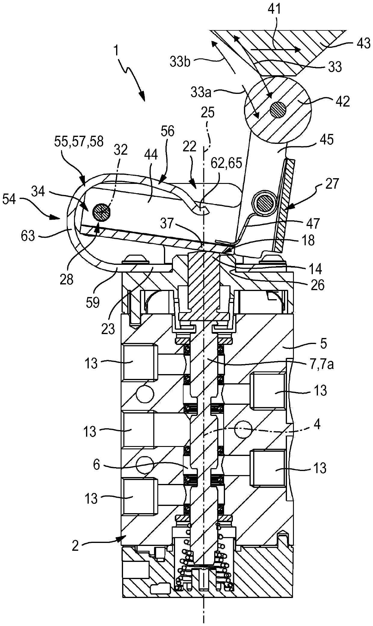
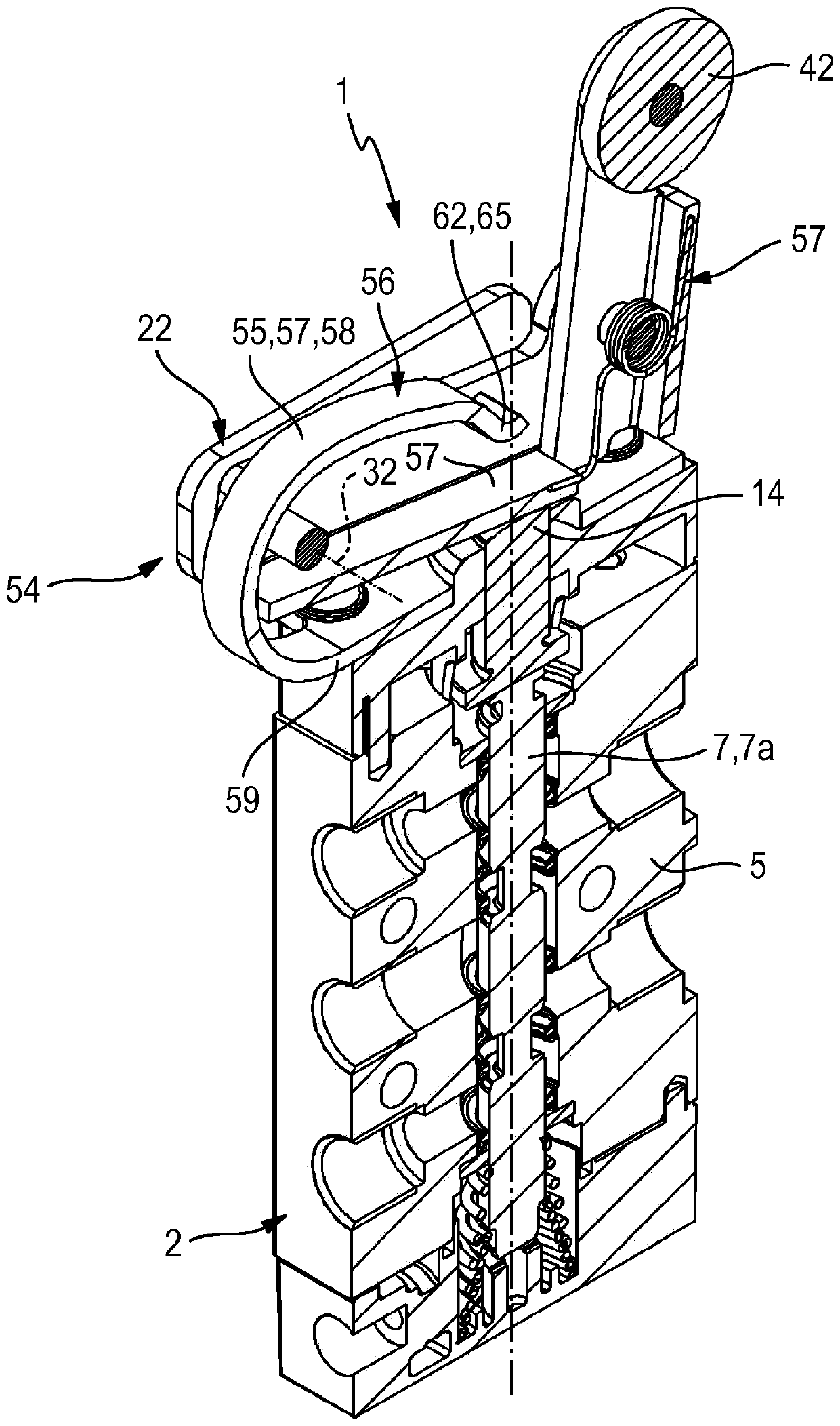
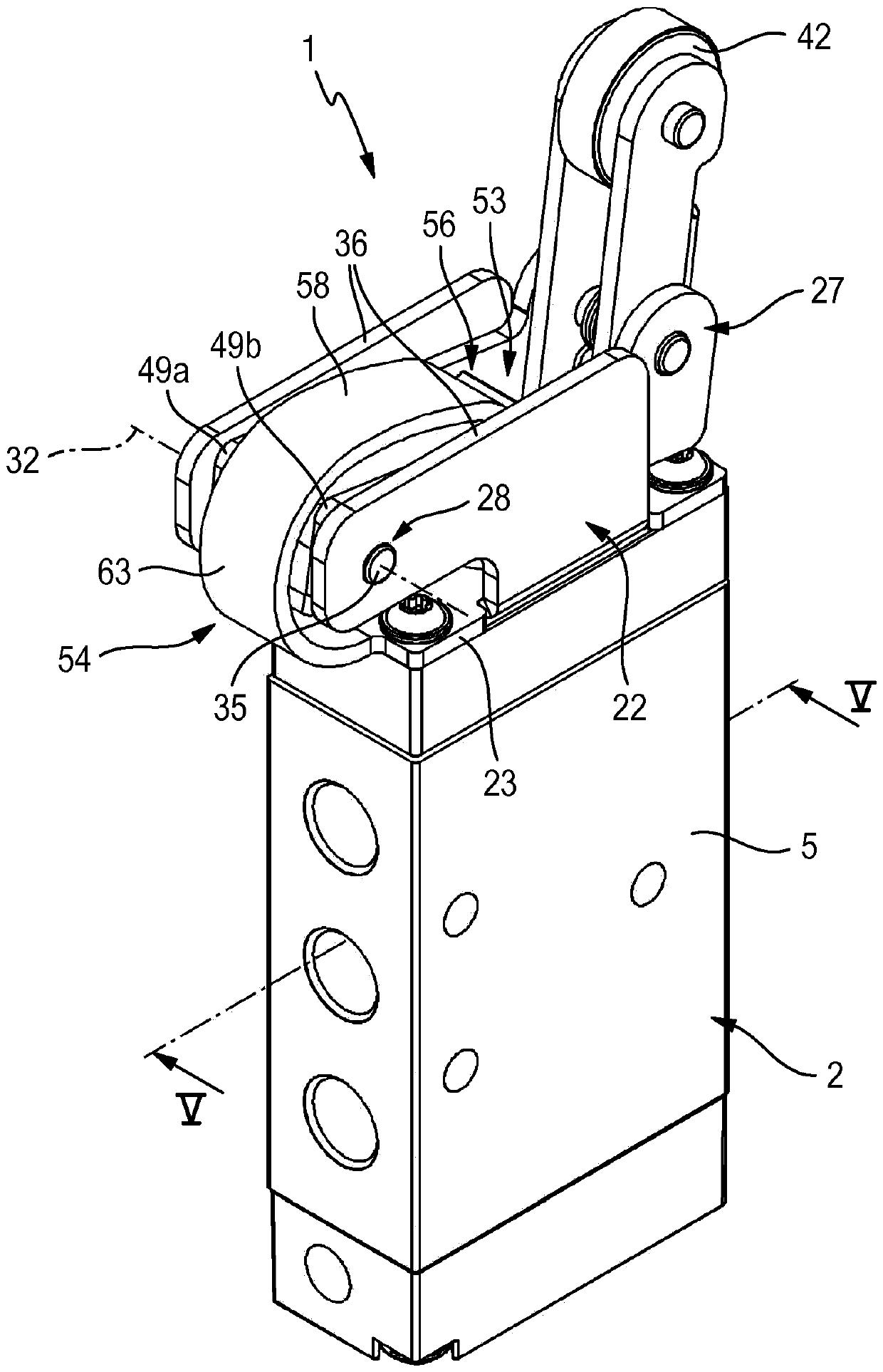
[0028] The roller lever valve 1 shown in the drawing has a valve unit 2 and a roller lever actuating device 3 for mechanically actuating the valve unit 2 .

[0029] The valve unit 2 has a longitudinal axis 4 . The roller lever actuation device 3 is preferably arranged on one of the two axial end sides of the valve unit 2 .

[0030] The valve unit 2 has a one-piece or multi-piece valve housing 5 , in which a valve chamber 6 is formed, in which a valve ring assembly 7 extends. In the present exemplary embodiment, the valve segment assembly 7 consists of a single valve segment 7a, but it can also comprise a plurality of valve segments. Within the range of the switching movement 8 indicated by the double arrow, the valve ring assembly 7 can be moved relative to the valve housing 5 in the axial direction of the longitudinal axis 4 and thus be switched between two switching positions. exist figure 2 and 3 In the first switching position of the valve link assembly 7 shown in the...


PUM


Abstract

The invention relates to a roller lever actuating device (3) and to a roller lever valve (1) equipped therewith. The roller lever actuating device (3) has a supporting base (22) and a roller lever (27) that can be pivoted in relation to the supporting base (22). The roller lever (27) can be pivoted from a base position into an actuation position, wherein the roller lever actuates a valve element assembly (7) of the roller lever valve (1). In the case of the opposite backward pivoting motion (33b), the roller lever (27) is braked by energy-absorbing means (55) of an energy-absorbing device (56) such that hard impacts and correspondingly heavy loading of the structure of the roller lever actuating device (3) are avoided.

Description

technical field [0001] The invention relates to a roller lever actuating device for a roller lever valve with a bearing base for fastening on a valve unit of a roller lever valve and a bearing base with drive rollers mounted pivotably with respect to a pivot axis on the bearing base Roller lever, wherein the roller lever is pivotable from a basic position into an actuating position in the range of a forward pivoting movement, and can be swiveled from the actuating position back into a basic position in a backward pivoting movement, wherein the roller The lever has at least one force output section spaced apart from the pivot axis, which is arranged to act in a pressing manner on the valve to be actuated associated with the roller lever valve in the case of a forward pivoting movement. On the control section of the link component. Furthermore, the invention relates to a roller lever valve equipped with such a roller lever actuating device. Background technique [0002] DE 1...

Claims


Application Information

Patent Timeline
Patent Type & Authority Patents(China)
IPC IPC(8): F16K31/524
CPCF16K31/52416F16K31/52483
Inventor F.施特恩斯S.佩希
Owner FESTO AG & CO KG
Learn More