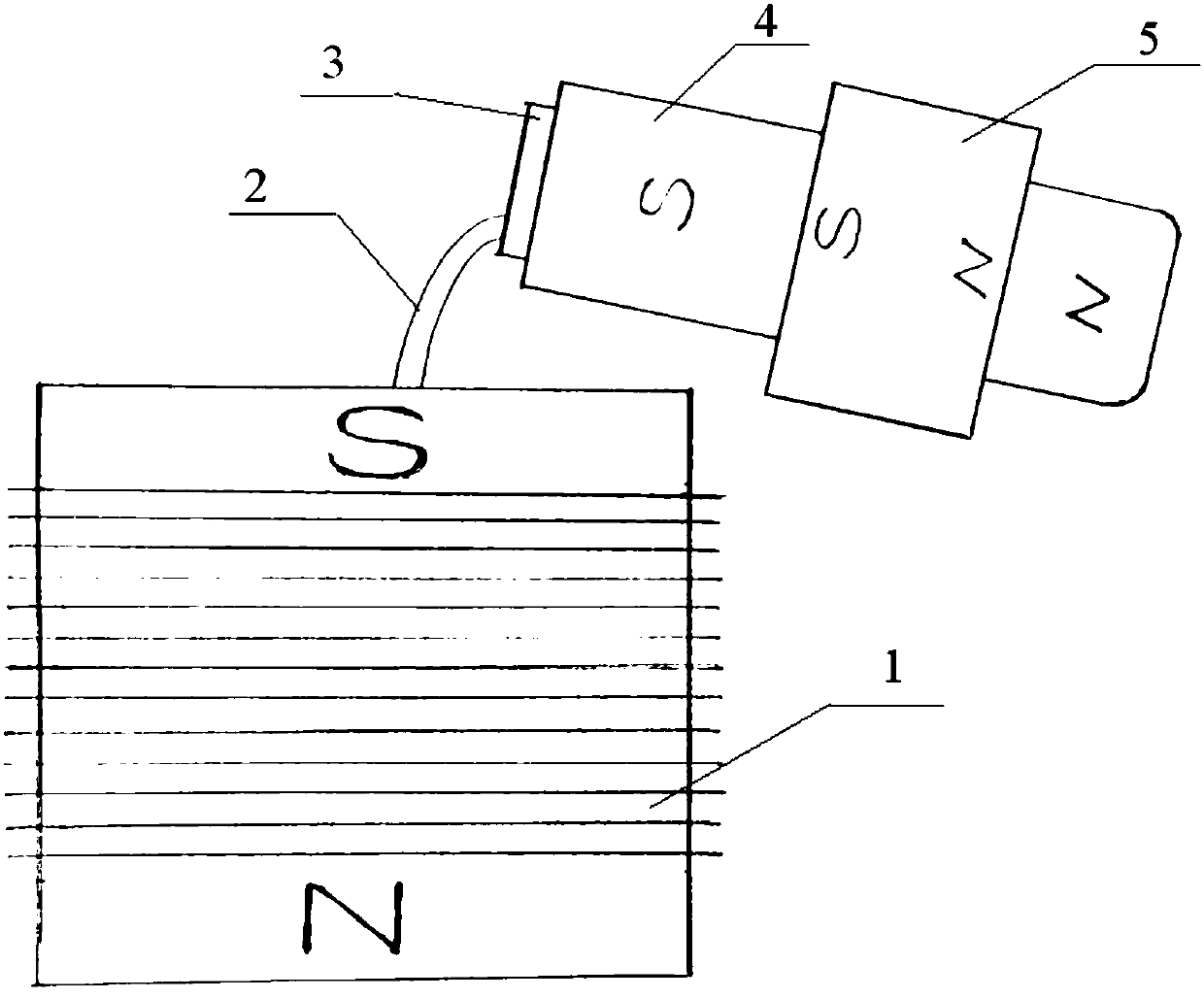
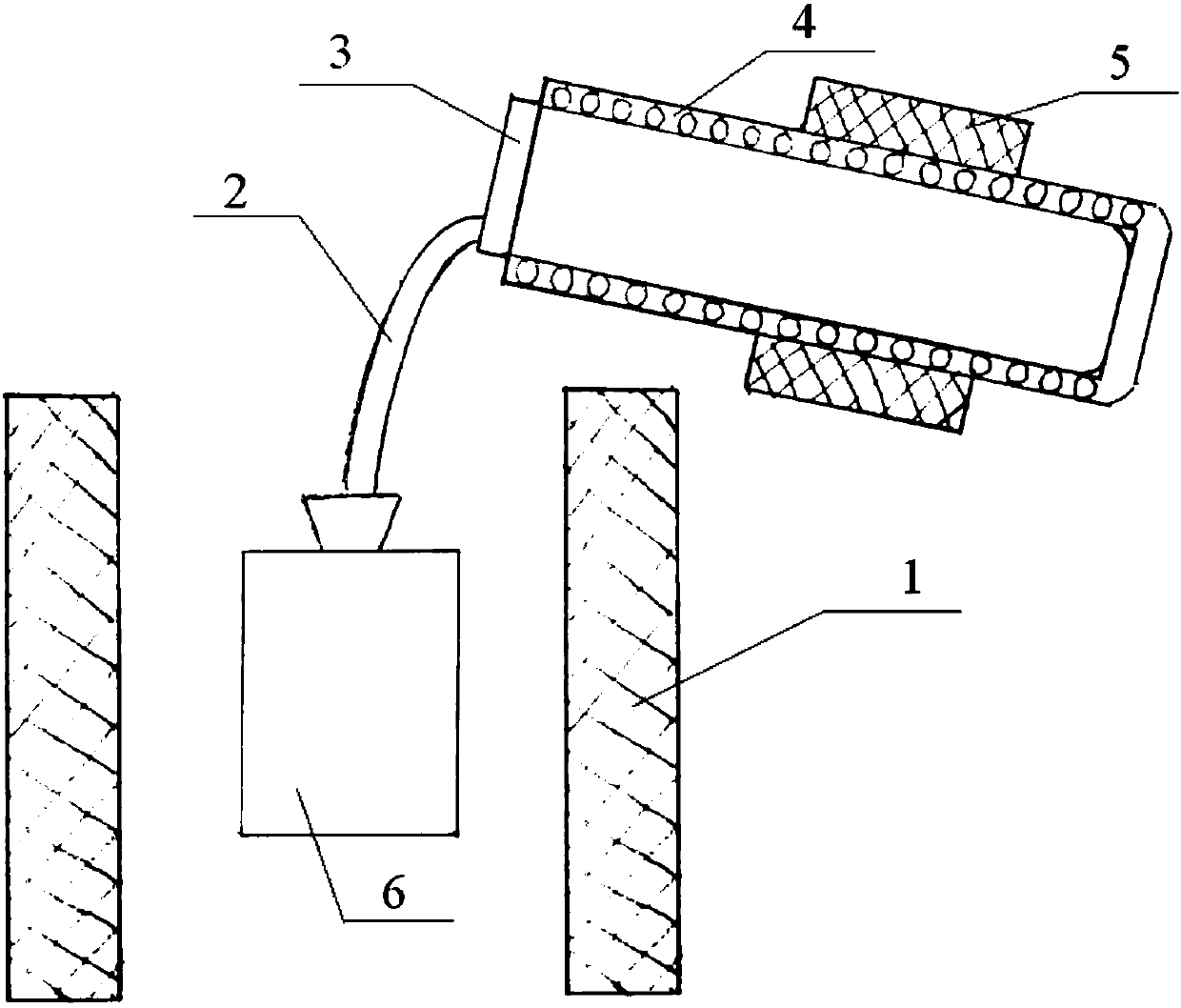
Casting furnace capable of utilizing non-synchronous bending for obtaining liquid deep undercooling

A synchronous bending and casting furnace technology, applied in foundry equipment, casting melt containers, manufacturing tools, etc., can solve problems such as inability to apply non-magnetic materials and inability to provide high magnetic field strength, to increase magnetic field strength, achieve small and The effect of uniform performance

Inactive Publication Date: 2018-05-15
赵京晨 +1
View PDF9 Cites 6 Cited by
  • Summary
  • Abstract
  • Description
  • Claims
  • Application Information

AI Technical Summary

Problems solved by technology

[0004] In view of the above analysis, the present invention aims to provide a casting furnace and method of using asynchronous bending to obtain deep subcooling of liquids, so as to solve the problem that the existing solidification equipment for obtaining deep subcooling of liquids cannot provide high magnetic field strength and cannot be applied The problem of being idle without magnetic materials

Method used


Image

  • Casting furnace capable of utilizing non-synchronous bending for obtaining liquid deep undercooling
  • Casting furnace capable of utilizing non-synchronous bending for obtaining liquid deep undercooling
  • Casting furnace capable of utilizing non-synchronous bending for obtaining liquid deep undercooling

Examples


Embodiment 1

[0071] Step 1. Bury the casting mold into a sand box, then push the sand box into a heating furnace and heat it to 1100°C for 4 hours;

[0072] Step 2. Open the furnace door, pull out the sand box embedded with the casting mold after the completion of step 1 out of the heating furnace, and place it on the casting mold base of the casting furnace with a plunger;

[0073] Step 3. Open the furnace cover, tilt the melting crucible at an angle of 45 degrees, push 50 kg of master alloy for melting and casting into the crucible along the mouth of the crucible, and at the same time add 10 grams of deoxidized carbon into the crucible, and then reset the crucible;

[0074] Step 4. The infrared temperature measurement and the galvanic temperature measurement response are normal, replace the blackened lens of the peephole, wipe the vacuum sealing surfaces, and then close the furnace cover and furnace door;

[0075] Step 5. Turn on the cooling water system, the inner cooling water pressure...

Embodiment 2

[0080] Step 1. Bury the casting mold into a sand box, then push the sand box into a heating furnace and heat it to 1200°C for 3 hours;

[0081] Step 2. Open the furnace door, pull out the sand box embedded with the casting mold after the completion of step 1 out of the heating furnace, and place it on the casting mold base of the casting furnace with a plunger;

[0082] Step 3. Open the furnace cover and tilt the melting crucible at an angle of 45 degrees; push 50 kg of master alloy for melting and casting into the crucible along the mouth of the crucible, and at the same time add 6 grams of deoxidized carbon into the crucible; then reset the crucible;

[0083] Step 4. The infrared temperature measurement and the galvanic temperature measurement response are normal, replace the blackened lens of the peephole, and wipe the vacuum sealing surfaces; then, close the furnace cover and furnace door;

[0084] Step 5. Turn on the cooling water system, the inner cooling water pressure ...


PUM

PropertyMeasurementUnit
diameteraaaaaaaaaa

Abstract

The invention discloses a casting furnace capable of utilizing non-synchronous bending for obtaining liquid deep undercooling. The casting furnace comprises a constant magnetic field coil which is located in the casting furnace, after direct-current power is applied, a static magnetic field is generated, a casting mold is placed in the static magnetic field. Meanwhile, the invention provides a usemethod of the casting furnace capable of utilizing non-synchronous bending for obtaining liquid deep undercooling. A smelting pot is provided with an induction coil exerting an alternating magnetic field and exerting the static magnetic field at the same time or independently, the static magnetic field strength in the area, close to the 1 / 2 position of the smelting pot, in the induction coil canreach 1 Tesla or above. On the casting central portion, that is, the metal liquid solidified casting center portion, the highest static magnetic field strength can reach 1 Tesla or above. The furnaceis not suitable for magnetic materials and also suitable for the non-magnetic materials.

Description

technical field [0001] The invention relates to the technical field of special casting equipment, in particular to a casting furnace for obtaining liquid deep and supercooling by asynchronous bending and a method of using the same. Background technique [0002] Achieving deep subcooling in a large volume of liquid has always been a dream of those engaged in special casting. The application number is 201110430497.7, and the title of the invention is a fully-filled casting method below the melting point, which discloses a method for suppressing the precipitation of solids in a liquid by using a low-frequency, low-power alternating magnetic field. However, the invention can make the liquid supercooled. The ability of the liquid is very limited, because in order to enhance the ability of the liquid to supercool, it is necessary to increase the strength of the magnetic field that suppresses the precipitation of the solid, but the enhancement of the magnetic field will be accompan...

Claims


Application Information

Patent Timeline
Patent Type & Authority Applications(China)
IPC IPC(8): B22D27/02B22D41/01B22D35/04
CPCB22D27/02B22D35/04B22D41/01
Inventor 赵京晨
Owner 赵京晨
Why Eureka
Try Eureka