Directional furnace and single crystal casting method both using asynchronous bending technology

A technology of simultaneous bending and technology, applied in the direction of single crystal growth, single crystal growth, chemical instruments and methods, etc., can solve the problem of low temperature gradient and achieve the effect of increasing temperature gradient

Inactive Publication Date: 2019-01-29
宁国市华成金研科技有限公司
View PDF6 Cites 6 Cited by
  • Summary
  • Abstract
  • Description
  • Claims
  • Application Information

AI Technical Summary

Problems solved by technology

[0004] In view of the above analysis, the embodiment of the present invention aims to provide an orientation furnace using asynchronous bending technology to solve the technical problem of low temperature gradient at the solid-liquid interface of the single crystal furnace in the Bridgman mode of existing industrial applications

Method used


Image

  • Directional furnace and single crystal casting method both using asynchronous bending technology
  • Directional furnace and single crystal casting method both using asynchronous bending technology
  • Directional furnace and single crystal casting method both using asynchronous bending technology

Examples


Embodiment 1

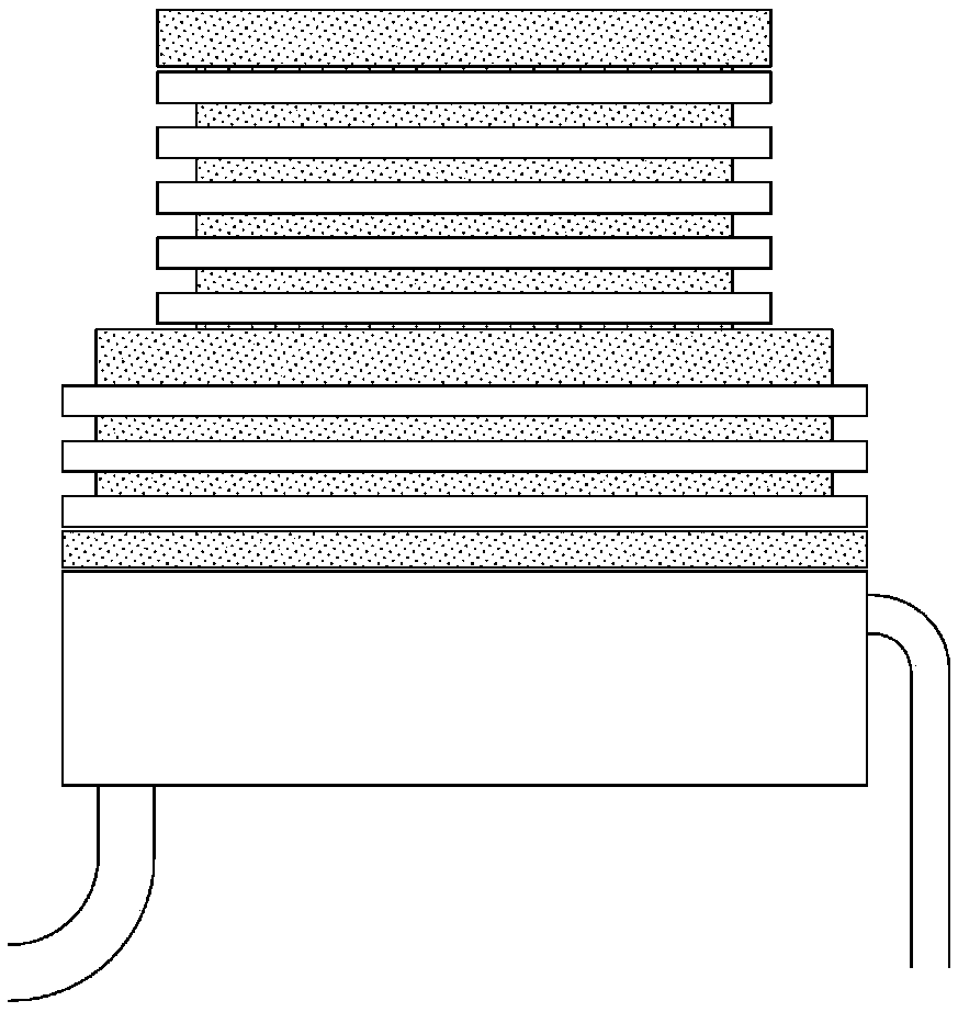
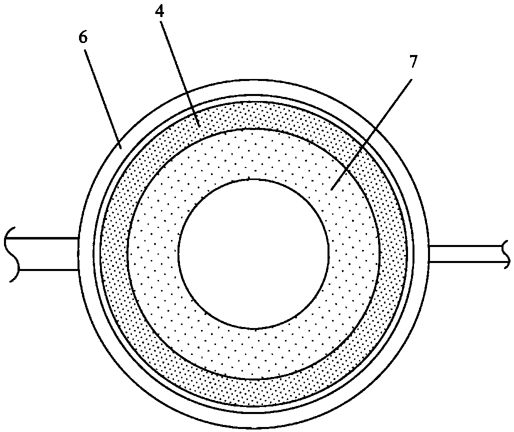
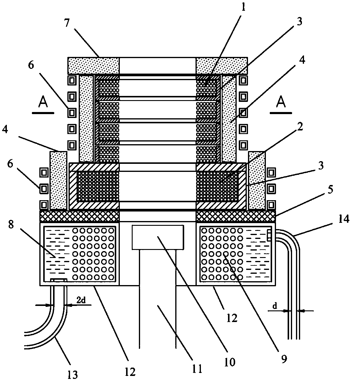
[0041] The present invention provides an orientation furnace using asynchronous bending technology, such as figure 1 and 3As shown, it includes a casting chamber, a reverse static magnetic field chamber 12 and a pull-down water-cooled crystallizer 10 located in the middle of the reverse static magnetic field chamber 12; the casting chamber includes a first energized coil 1, a second energized coil 2 and a bearing The slot 3, the first energized coil 1 and the second energized coil 2 internal space constitute a static magnetic field application area, and the static magnetic field application area is also a temperature heating area; the first energized coil 1 and the second energized coil 2 are respectively located in the bearing groove 3, The first energization coil 1 is located above the second energization coil 2; the reverse static magnetic field chamber 12 includes a third energization coil 9 and an insulating cooling unit, and the third energization coil forms a static mag...

Embodiment 2

[0079]S1. Place 10 kg of master alloy in the melting crucible, then put 1 gram of deoxidized carbon on the master alloy, then check whether the temperature measuring device and peephole are normal and available, turn on the furnace body and vacuum system, and turn on the square coolant copper Tube 6 and the insulation cooling unit of the pull-down water-cooled crystallizer 10, and open the cooling water circulation system of the square cooling liquid copper pipe 6 and the pull-down water-cooled crystallizer 10, and open the transformer of the ring-shaped non-magnetic stainless steel reverse static magnetic field chamber 12 for insulation cooling Forced circulation system of oil 8 and external circulation water cooling system for forced cooling of the cooling oil.

[0080] S2. Place the casting mold shell on the drop-down water-cooled crystallizer 10 below the casting chamber, align the center to ensure that the casting mold shell will not scratch the surrounding devices when it...


PUM


Abstract

The invention relates to a directional furnace adopting an asynchronous bending technology, and belongs to the technical field of casting equipment. The present invention solves the technical problemthat heat and magnetic lines of force in a mold chamber of the directional furnace pass through a magnetic receptor thermal-insulating layer, thereby limiting increase in the temperature gradient at the location. The directional furnace comprises a mold chamber, a reverse static magnetic field chamber and a pull-down water-cooling crystallizer; the mold chamber comprises a static magnetic field application zone and a temperature heating zone; a magnetic receptor thermal-insulating layer is disposed between the mold chamber and the reverse static magnetic field chamber; a portion of a static magnetic field in the mold chamber forms a leakage magnetic field through the magnetic receptor thermal-insulating layer, and the leakage magnetic field has a same magnetic field strength and an opposite magnetic direction compared with the static magnetic field in the reverse static magnetic field chamber; the reverse static magnetic field chamber is further provided with an insulation cooling unitfor cooling the reverse static magnetic field chamber; and a molding shell is arranged above the pull-down water-cooling crystallizer for casting a single crystal. The directional furnace of the invention is used to increase the temperature gradient at a solid-liquid interface during solidification of master alloy.

Description

technical field [0001] The invention relates to the technical field of precision casting equipment, in particular to an orientation furnace and a single crystal casting method using asynchronous bending technology. Background technique [0002] The application field of the present invention is a directional solidification furnace or a single crystal furnace in the field of precision casting equipment, and it is a Bridgman type directional solidification furnace or a single crystal furnace. The performance of the directional solidification furnace mainly depends on the temperature gradient of the solid-liquid interface where the crystal grows. [0003] At present, the industry's efforts to improve the temperature gradient of the solid-liquid interface for crystal growth in the Bridgman-style directional solidification furnace have reached the limit. Since the literature reports that the temperature gradient can reach 50-70 ° C in the 1970s, this has not been seen for many yea...

Claims


Application Information

Patent Timeline
Patent Type & Authority Applications(China)
IPC IPC(8): C30B11/00C30B29/52B22D27/04B22D27/02
Inventor 赵京晨程国华赵晓腾吴文京
Owner 宁国市华成金研科技有限公司
Why Eureka
Try Eureka