
Planar flexible thermoelectric power generation structure

A thermoelectric power generation, planar technology, applied in the directions of generators/motors, electrical components, thermoelectric device components, etc., can solve the problem that the thermoelectric power generation structure is not flexible, the temperature difference between the hot and cold ends of the thermoelectric arm is small, and the thermoelectric arm does not enhance heat dissipation, etc. problem, to achieve the effect of simple manufacturing process, large thermoelectric figure of merit, and low cost

Inactive Publication Date: 2014-12-03
ZHEJIANG UNIV
View PDF6 Cites 14 Cited by
  • Summary
  • Abstract
  • Description
  • Claims
  • Application Information

AI Technical Summary

Problems solved by technology

[0008] The purpose of the present invention is to provide a planar flexible thermoelectric power generation structure, which is used to solve the problem that there is no thermal isolation between the cold end and the hot end of the thermoelectric arm in the technology, the cold end of the thermoelectric arm does not strengthen heat dissipation, and the temperature difference between the cold end and the hot end of the thermoelectric arm is relative. Small, thermoelectric power generation structure is not flexible and other issues

Method used


Image

  • Planar flexible thermoelectric power generation structure
  • Planar flexible thermoelectric power generation structure
  • Planar flexible thermoelectric power generation structure

Examples


Embodiment Construction

[0033] The present invention will be further described below in conjunction with the accompanying drawings and implementation examples.

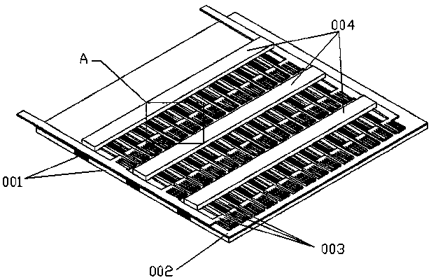
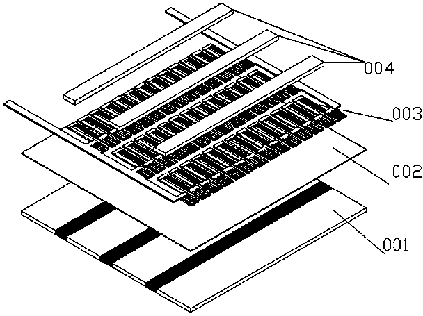
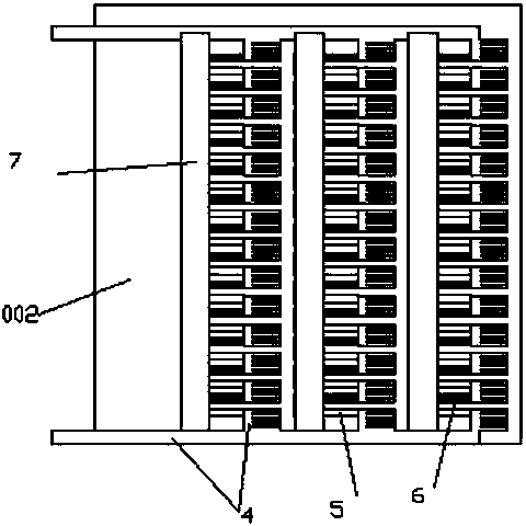
[0034] Such as figure 1 , figure 2 , image 3 , Figure 4 , Figure 5 As shown, the present invention includes a heat conduction layer 001, an insulation layer 002, a power generation layer 003, and a hot end protection layer 004 laid sequentially from bottom to top, an insulation layer 002 is laid on the heat conduction layer 001, and a power generation Layer 003, the power generation layer 003 is covered with a hot end protection layer 004; the heat conduction layer 001, the insulating layer 002, the power generation layer 003 and the hot end protection layer 004 are all made of flexible materials, the first flexible material 1 and the second flexible material 2 The thermal conduction layer 001 is closely spaced, the first flexible material 1 and the second flexible material 2 are arranged in parallel, the hot end protection layer 004...


PUM


Abstract

The invention discloses a planar flexible thermoelectric power generation structure which includes a thermal conduction layer, an insulating layer, a power generation layer and a hot-end protective layer, which are sequentially arrayed and laid from bottom to top. All of the thermal conduction layer, the insulating layer, the power generation layer and the hot-end protective layer adopt flexible materials. A first flexible material and a second flexible material are closely arrayed alternatively so that the thermal conduction layer is formed. The hot-end protective layer is a flexible insulating strip. Both of the heat conduction factors of the first flexible material and the flexible insulating strip are lower than the heat conduction factor of the second flexible material. The structure increases protection of a hot end and heat radiation of a cold end, improves the temperature gradient of a thermoelectric power generator and further improves an output power and an output voltage. The thermal conduction layer provides a temperature gradient needed by the thermoelectric power generator and has a support function; the flexible materials are adopted so that compared with a rigid thermoelectric power generation device, the power generation structure is flexible, light and convenient and capable of better fitting to the plane; and the power generation structure is simple in structure and manufacturing process and capable of realizing mass production, and has an excellent application prospect.

Description

technical field [0001] The invention relates to a thermoelectric power generation structure, in particular to a planar flexible thermoelectric power generation structure. Background technique [0002] The energy crisis is becoming more and more serious, and it is urgent to actively promote and promote the use of clean and renewable energy. As a widely distributed energy source in nature, thermal energy is generated all the time. However, the utilization of thermal energy by human beings is far from enough at present, and the utilization rate is extremely low. It is of great research value to make full use of these unused heat energy in nature and convert it into electrical energy that can be stored and directly used. [0003] Since the discovery of the Seebeck effect in 1821, with the continuous research on thermoelectric materials, thermoelectric technology has received more and more attention. Thermoelectric generators use the Seebeck effect of thermoelectric semiconduc...

Claims


Application Information

Patent Timeline
Patent Type & Authority Applications(China)
IPC IPC(8): H01L35/02H01L35/28H01L35/34H02N11/00H10N10/80H10N10/01H10N10/10
Inventor 梅德庆刘海燕史尧光姚喆赫陈子辰
Owner ZHEJIANG UNIV
Learn More