Oriented solidification casting method and apparatus

A directional solidification and mold technology, applied in the field of casting, can solve the problems of inability to judge the dynamic position, part shape and size restrictions, and no information collection system, etc. It is suitable for mass production, large temperature gradient, and wide application range Effect

Inactive Publication Date: 2004-09-08
周照耀
View PDF2 Cites 14 Cited by
  • Summary
  • Abstract
  • Description
  • Claims
  • Application Information

AI Technical Summary

Problems solved by technology

The disadvantage of the aforementioned method is that the structure of the equipment is complex, there is no information collection system, and it is impossible to judge the dynamic positions of the solid phase region, crystallization region and liquid phase region of the solidified material during the solidification process of the liquid metal. During the casting process, the mold or The speed of relative movement of castings can only be determined by experience, and the operation process is difficult to control. The shape and size of the manufactured parts are limited by the structure of the equipment, and only cylindrical parts or simple shape castings can be produced.

Method used


Image

  • Oriented solidification casting method and apparatus
  • Oriented solidification casting method and apparatus
  • Oriented solidification casting method and apparatus

Examples


Embodiment 1

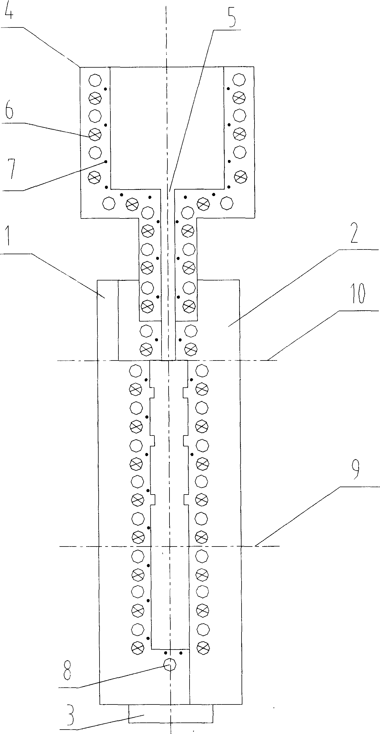
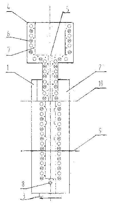
[0025] What is to be prepared in this embodiment is the directionally solidified thin plate casting with ribs. The mold used is as figure 1 shown in figure 1 Among them, the module 1 and the module 2 are locked by the locking buckle 3, and they are combined into a mold. The lower end of the riser 4 is inserted into the mold, and the riser 4 is provided with a liquid material input port 5, and the mold wall and the riser 4 Hollow cooling passages 8 and heating elements 6 are arranged alternately in the walls. The hollow cooling passages 8 are connected to the coolant supply components through control valves. The heating elements 6 are connected to the power supply through switches. The control valves and switches are connected to the control parts. connection, the mold is provided with a temperature sensor 7, and the temperature sensor 7 is closely attached to a position close to the mold wall of the cavity.

[0026] The preparation process of this directionally solidified th...

Embodiment 2

[0028] Present embodiment is identical with embodiment 1 except following process: figure 1 A sealing cover is arranged on the middle riser 4 to seal the riser 4, and then compressed gas is injected into the riser 4, and a compressive stress of 1.5 MPa is applied to the aluminum alloy liquid surface in the riser 4 through the gas.

Embodiment 3

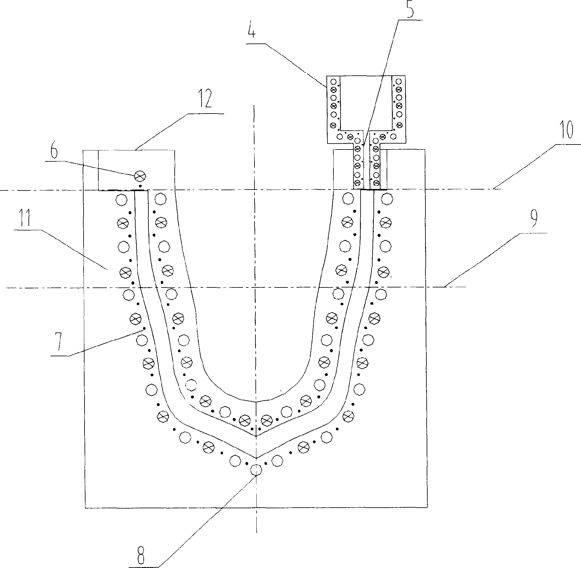
[0030] What this embodiment is to prepare is a directionally solidified shell-shaped casting. The mold used is as figure 2 shown in figure 2 Among them, the module 11 and the module 12 are locked by screws to form a mold, the riser 4 is inserted into one end of the mold, and the riser 4 is provided with a liquid material input port 5, which is in the wall of the mold and the wall of the riser 4 Hollow cooling passages 8 and heating elements 6 are arranged alternately. The hollow cooling passages 8 are connected to the coolant supply components through control valves. The heating elements 6 are connected to the power supply through switches. The control valves and switches are connected to the control parts. A temperature sensor 7 is arranged in the middle, and the temperature sensor 7 is closely attached to a position close to the mold wall of the cavity.

[0031] The preparation process of this directionally solidified shell-shaped casting is specifically as follows: firs...


PUM


Abstract

The oriented solidification casting method includes the following steps: pre-heating the mold with controllable local temperature, feeding the molten metal into the mold cavity via the feeding port, controlling the local temperature of the mold to start cooling while maintaining the rest parts of the mold in heat maintaining state, collecting the data via sensors to judge the positions of solidified regions, crystallized regions and liquid phase regions, and controlling the local temperature of the mold part contacting the liquid area to be solidified to make the metal liquid in overheat state while making the mold part contacting the crystallized material disperse heat. The oriented solidification casting apparatus includes mold with hollow cooling channel and heating element. The present invention is simple and controllable and may be used in making large complicated casting, and the product has excellent structure.

Description

technical field [0001] The invention belongs to the technical field of casting, and in particular relates to a directional solidification casting method and a device thereof. Background technique [0002] Since the directional solidification method was first used to study planar and cellular solidification in 1952, directional solidification technology has developed rapidly. This technique was originally used to eliminate the transverse grain boundaries generated during the crystallization process, thereby improving the unidirectional mechanical properties of the material. Because directional solidification technology can obtain some materials with special structure orientation and excellent performance, the main application of current directional solidification technology is to produce castings with uniform columnar crystal or single crystal structure, especially in the aviation field to produce superalloy engine blades Compared with castings obta...

Claims


Application Information

Patent Timeline
Patent Type & Authority Applications(China)
IPC IPC(8): B22D27/04
Inventor 周照耀
Owner 周照耀
Why Eureka
Try Eureka