
Device for mounting and dismounting shaft parts

A technology for loading and unloading devices and parts, which is applied to hand-held tools, manufacturing tools, etc., can solve problems such as inability to adjust, limited application scope, and inability to achieve fine adjustment, and achieves the effect of reducing damage and reducing the difficulty of loading and unloading.

Pending Publication Date: 2018-05-15
QINGDAO MESNAC ELECTROMECHANICAL ENG
View PDF17 Cites 3 Cited by
  • Summary
  • Abstract
  • Description
  • Claims
  • Application Information

AI Technical Summary

Problems solved by technology

The structure of the device is relatively simple, and can only be adjusted in the vertical direction, and other directions can only be aligned by hand pushing, and fine

Method used


Image

  • Device for mounting and dismounting shaft parts
  • Device for mounting and dismounting shaft parts
  • Device for mounting and dismounting shaft parts

Examples


Embodiment Construction

[0028] It should be noted that, in the case of no conflict, the embodiments in the present application and the features in the embodiments can be combined with each other. The present invention will be described in detail below with reference to the accompanying drawings and examples.

[0029] It should be noted that the terminology used here is only used to describe specific implementations, and is not intended to limit the exemplary implementations according to the present application. As used herein, unless the context clearly dictates otherwise, the singular is intended to include the plural, and it should also be understood that when the terms "comprising" and / or "comprising" are used in this specification, they mean There are features, steps, operations, means, components and / or combinations thereof.

[0030] It should be noted that the terms "first" and "second" in the description and claims of the present application and the above drawings are used to distinguish simi...


PUM


Abstract

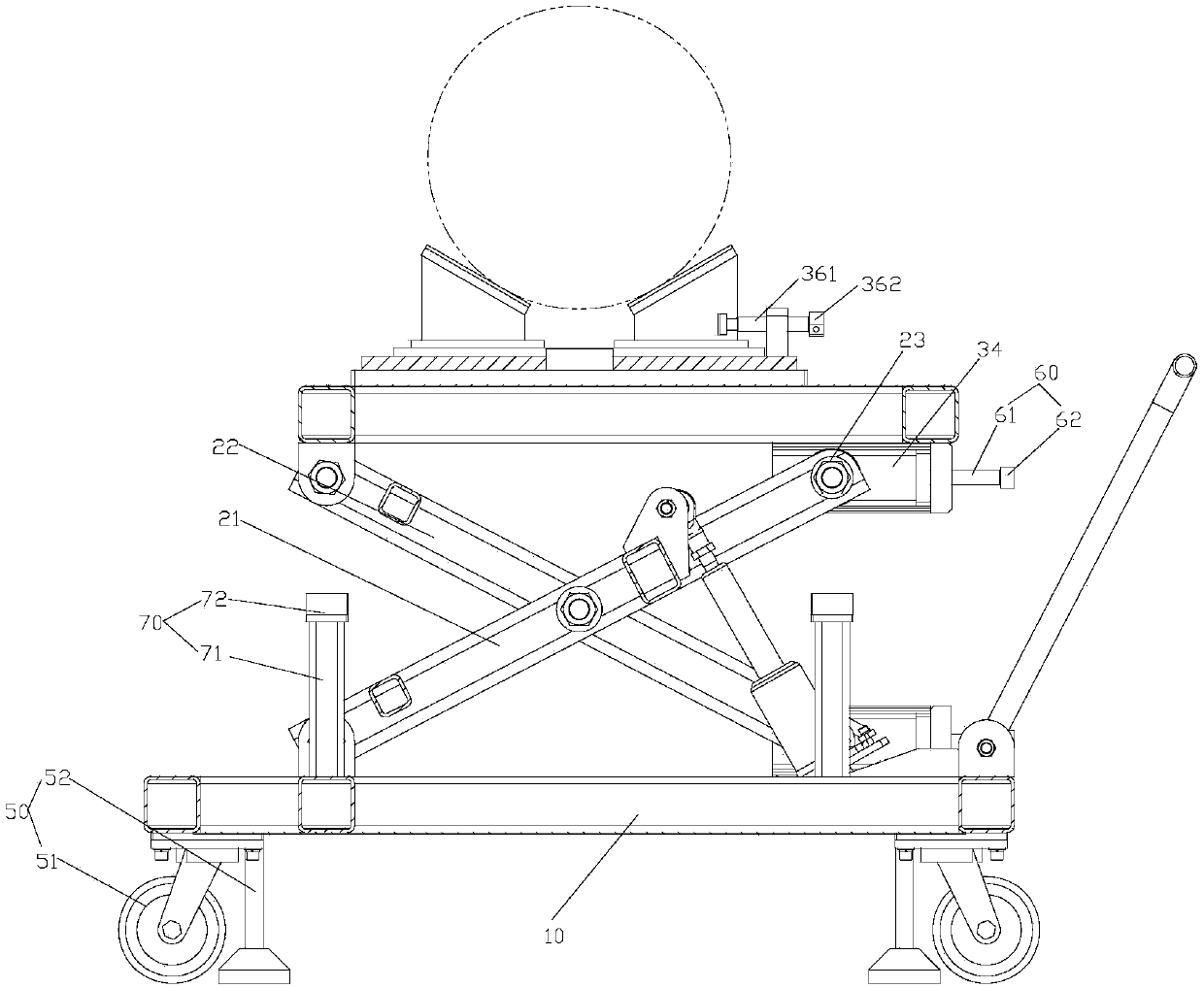
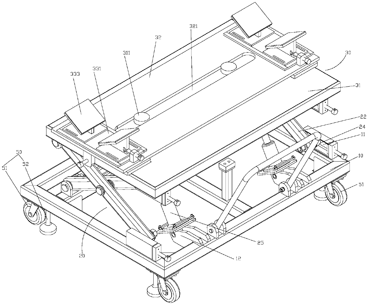
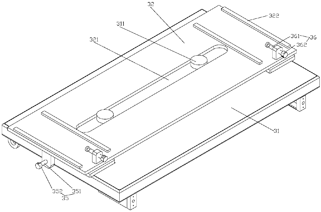
The invention provides a device for mounting and dismounting shaft parts. The device comprises a base, a lifting mechanism and a horizontal adjustment stand, wherein a movable part is mounted at the bottom of the base; the lifting mechanism is mounted on the base; the horizontal adjustment stand is mounted at the top end of the lifting mechanism; an adjustable support is arranged on the horizontaladjustment stand and the adjustable support comprises at least two support mechanisms arranged in the length direction of the horizontal adjustment stand; the support mechanisms comprise two supportstructures which are moved relatively; and the two support structures are commonly encircled into a positioning space for bearing the shaft parts. The device for mounting and dismounting shaft parts disclosed by the invention can be adapted to mounting and dismounting of the shaft parts of multiple specifications, and can be conveniently and flexibly adjusted in the multiple directions; and moreover, the mounting and dismounting difficulty is reduced, and damage to the shaft parts is reduced.

Description

technical field [0001] The invention relates to the technical field of loading and unloading devices, in particular to a loading and unloading device for shaft parts. Background technique [0002] The OTR tire building machine needs to replace the building drum and even the main shaft during installation and commissioning, daily maintenance and production of tires of different specifications. OTR tire drum shaft parts weigh from hundreds of kilograms to several tons, and are generally assembled and disassembled by large-scale lifting equipment such as workshop driving, cranes or forklifts. Such lifting equipment is relatively heavy and difficult to meet the drum shaft parts. Requirements for precision assembly of parts, inconvenient adjustment of lifting height and parallelism, low loading and unloading efficiency, easy eccentricity of dragging when moving parallel to the main shaft direction, thus scratching the surface of parts, and excessive operation may cause the drum s...

Claims


Application Information

Patent Timeline
IPC IPC(8): B25B27/00
CPCB25B27/00
Inventor 武守涛刘坤邬成亮卜庆勇姜春晖
Owner QINGDAO MESNAC ELECTROMECHANICAL ENG
Learn More