Machine room

A computer room and cabinet technology, which is applied in the communication field, can solve the problems of insufficient flexibility and versatility of the mounted equipment in the computer room, and achieve the effect of flexible mounted equipment, strong versatility, and firm mounted equipment

Inactive Publication Date: 2018-05-15
CHINA TOWER CO LTD
View PDF4 Cites 0 Cited by
  • Summary
  • Abstract
  • Description
  • Claims
  • Application Information

AI Technical Summary

Problems solved by technology

[0003] In order to solve the above technical problems, the present invention provides a computer room, which solves the problem of insufficient flexibility and versatility of the equipment mounted in the computer room

Method used


Image

  • Machine room
  • Machine room
  • Machine room

Examples


Embodiment Construction

[0030] Exemplary embodiments of the present invention will be described in more detail below with reference to the accompanying drawings. Although exemplary embodiments of the present invention are shown in the drawings, it should be understood that the invention may be embodied in various forms and should not be limited to the embodiments set forth herein. Rather, these embodiments are provided for more thorough understanding of the present invention and to fully convey the scope of the present invention to those skilled in the art.

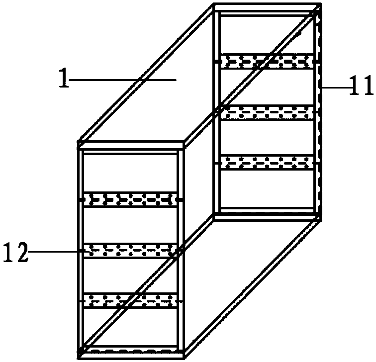
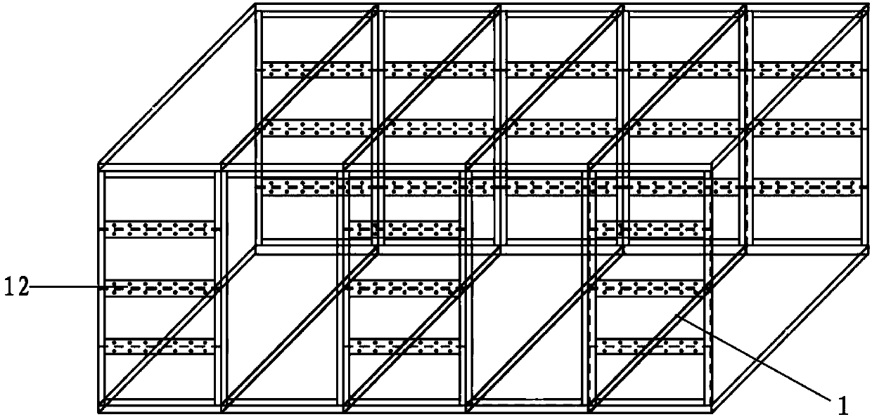
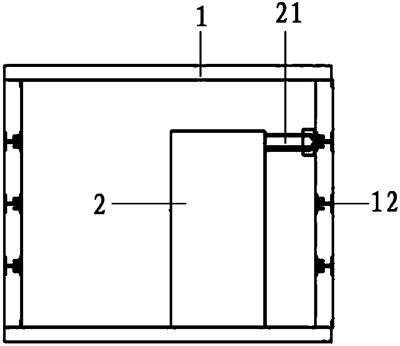
[0031] Such as figure 1 As shown, the embodiment of the present invention provides a machine room, including an assembly unit 1, wherein the assembly unit 1 includes:

[0032] A plurality of splicing plates, each of which is provided with a supporting keel 11 inside and on the edge; the multiple splicing plates are connected by the supporting keel 11 on the edge, and are formed to form openings on opposite two end faces, Other accommodating sp...


PUM


Abstract

The invention discloses a machine room, comprising an assembly unit, wherein the assembly unit comprises a plurality of splice plates; each of the inside and edge of each splice plate is provided witha support keel, the splice plates are connected through the support keels at the edges, forming a receiving space having two opposite ends opened and other ends closed, wherein at least one splice plate is provided with at least one connection rack that is provided with at least one bolt hole. The machine room according to the embodiment may be expanded to different sizes via the multiple assembly units so as to mount devices having different specification numbers; the keels at the inside and edges of the splice plates forming the assembly unit allow the devices to be mounted on the splice plates more firmly; the connection racks made of I-beams on the splice plates impart various functions, such as shock resistance and theft prevention, to the machine room, devices can be flexibly mounted, and the machine room is highly universal.

Description

technical field [0001] The present invention relates to the communication field, in particular to a computer room. Background technique [0002] Currently existing computer room walls have no keel inside, so they are usually not used for mounting equipment, and cannot meet the requirements for mounting equipment on the internal walls of the computer room. The usual method is to add steel plates to the inner and outer sides, which has limited bearing capacity and will cause damage to the wall. The biggest disadvantage of the current computer room is that the flexibility and versatility of the mounting equipment is insufficient. Usually, it needs to be designed before leaving the factory, and the mounting bracket needs to be re-customized to replace the equipment. At the same time, the expansion function of the computer room is lacking, and it is not possible to add cable racks and equipment racks according to actual needs. It is also difficult to realize the expansion of an...

Claims


Application Information

Patent Timeline
Patent Type & Authority Applications(China)
IPC IPC(8): E04H5/02G08B13/183
CPCE04H5/02G08B13/183
Inventor 农军钟浩
Owner CHINA TOWER CO LTD
Why Eureka
Try Eureka