
Communication equipment bracket

A communication equipment and bracket technology, applied in the field of auxiliary support devices for communication equipment, can solve problems such as inability to adapt, poor adaptability, and loose overall connection, and achieve the effects of easy adjustment of angle, realization of height, and wide applicability

Inactive Publication Date: 2018-05-15
南京云清普为通信科技有限公司
View PDF0 Cites 4 Cited by
  • Summary
  • Abstract
  • Description
  • Claims
  • Application Information

AI Technical Summary

Problems solved by technology

[0002] As we all know, communication equipment is widely used in various fields, and the communication equipment bracket is an auxiliary device for supporting it, and it is widely used. The present invention is mainly aimed at the auxiliary supporting device for mobile phones when used in cars. Elaboration and description; the existing communication equipment bracket includes a magnetic suction block, a suction cup and a connecting frame, one end of the connecting frame is connected with the suction cup, and the other end of the connecting frame is connected with the magnetic suction block; The suction block absorbs the communication equipment for use; however, it is found in its use that the communication equipment must be made of metal through the magnetic absorption of the magnetic block, which is greatly restricted, and its angle and height cannot be adjusted. Therefore, it cannot adapt to users with different requirements, and the adaptability is poor, and the way of fixing the suction cup to the inside of the car body also makes the overall connection not tight, and it is easy to loosen and fall off

Method used


Image

  • Communication equipment bracket
  • Communication equipment bracket

Examples


Embodiment Construction

[0014] The following will clearly and completely describe the technical solutions in the embodiments of the present invention with reference to the accompanying drawings in the embodiments of the present invention. Obviously, the described embodiments are only some, not all, embodiments of the present invention.

[0015] In describing the present invention, it should be understood that the terms "upper", "lower", "front", "rear", "left", "right", "top", "bottom", "inner", " The orientation or positional relationship indicated by "outside", etc. is based on the orientation or positional relationship shown in the drawings, and is only for the convenience of describing the present invention and simplifying the description, rather than indicating or implying that the referred device or element must have a specific orientation, so as to Specific orientation configurations and operations, therefore, are not to be construed as limitations on the invention.

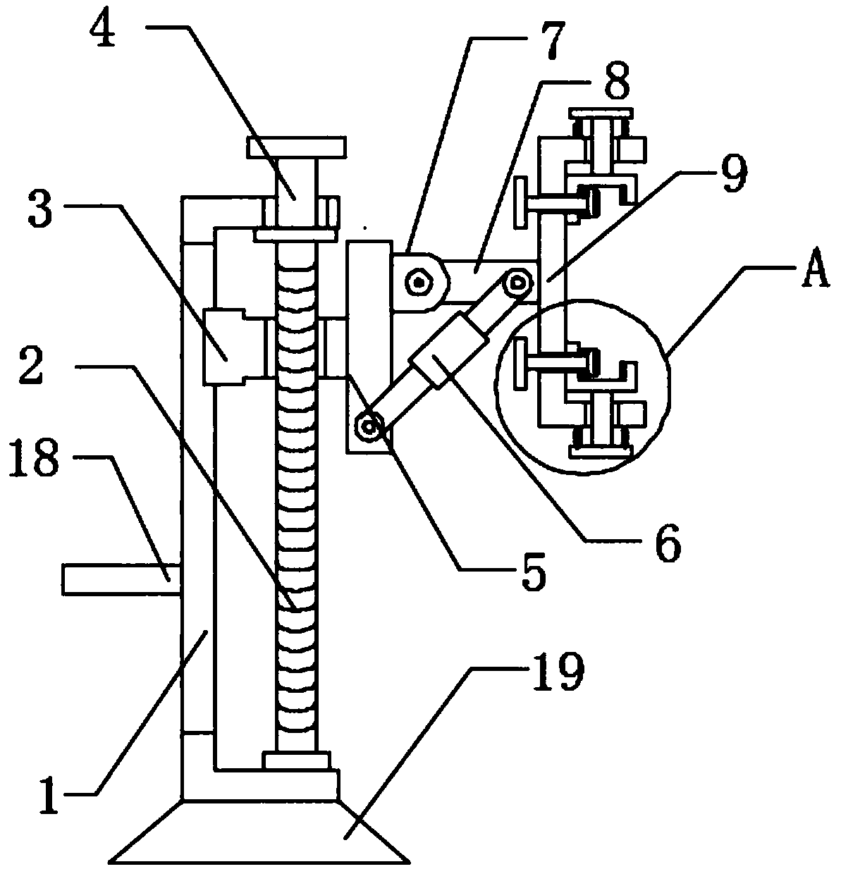
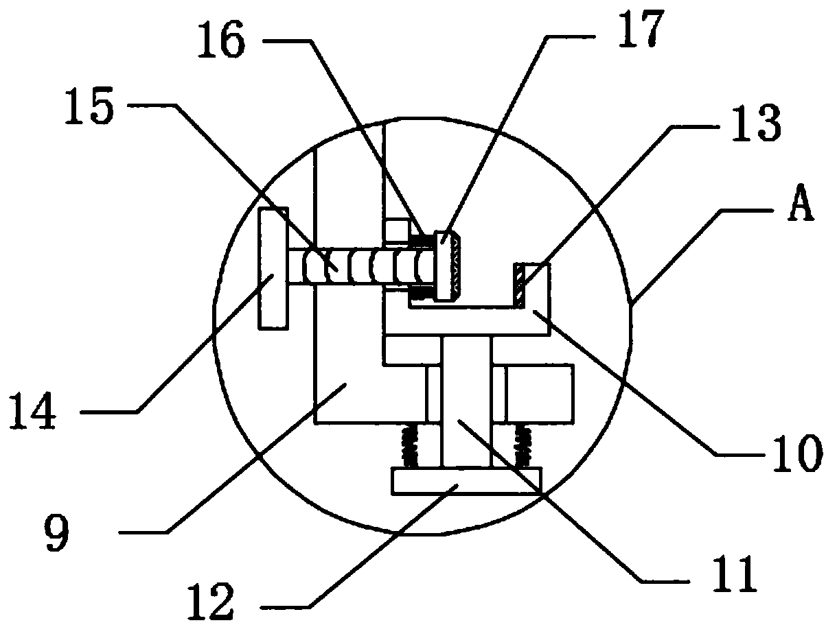
[0016] Such as Figure 1...


PUM


Abstract

The invention discloses a communication equipment bracket which comprises a main board, wherein a placement groove is formed in the main board; a first screw is rotationally connected in the placementgroove; a handle is arranged on one side of the main board; one side of the handle penetrates through the top of the main board and is fixedly connected with the first screw; a threaded block is connected on the first screw in a sliding and sleeving manner; a chute corresponding to the threaded block is formed in the inner bottom of the main board; a linkage plate is fixedly connected to one side, which is far away from the inner bottom of the main board, of the threaded block; a fixing block is fixedly connected onto the linkage plate; a movable rod is arranged on one side of the fixing block; a clamping groove corresponding to the movable rod is formed in the fixing block; the movable rod is rotationally connected with the inner side wall of the clamping groove by virtue of a rotating shaft; the movable rod is rotationally connected with the linkage plate by virtue of a turnbuckle; and a U-shaped bracket is fixedly connected to one end, which is far away from the fixing block, of the movable rod. The communication equipment bracket disclosed by the invention is capable of fixing communication equipment of different sizes and performing angle and height adjustment, and is wide inapplicability.

Description

technical field [0001] The invention relates to the technical field of auxiliary support devices for communication equipment, in particular to a bracket for communication equipment. Background technique [0002] As we all know, communication equipment is widely used in various fields, and the communication equipment bracket is an auxiliary device for supporting it, and it is widely used. The present invention is mainly aimed at the auxiliary supporting device for mobile phones when used in cars. Elaboration and description; the existing communication equipment bracket includes a magnetic suction block, a suction cup and a connecting frame, one end of the connecting frame is connected with the suction cup, and the other end of the connecting frame is connected with the magnetic suction block; The suction block absorbs the communication equipment for use; however, it is found in its use that the communication equipment must be made of metal through the magnetic absorption of t...

Claims


Application Information

Patent Timeline
IPC IPC(8): H04M1/04B60R11/02
CPCH04M1/04B60R11/0241B60R2011/008
Inventor 许四清陈启云
Owner 南京云清普为通信科技有限公司
Learn More