Plate punching mechanism, intelligent clamping device and using method
A clamping device and plate technology, used in positioning devices, clamping, metal processing machinery parts, etc., can solve the problems of plate deviation, complex structure, insufficient maneuverability, etc., to improve the reliability of operation and the whole process of operation. Simple, low-cost effects
- Summary
- Abstract
- Description
- Claims
- Application Information
AI Technical Summary
Problems solved by technology
Method used
Image
Examples
Embodiment approach 1
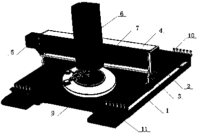
[0020] as attached figure 1 As shown, the plate punching mechanism includes a base 1, and the base 1 is provided with several support strips 2, and the first support strip and the second support strip are placed at intervals and form a slideway The inner edge of the other side of the base 1 relative to the slideway forms a slide groove, and the first and second slide plates 3 are slidably matched with the slideway and the slide groove respectively, and the The two slide plates 3 are provided with brackets 4, one side and / or the other side of the brackets 4 are provided with drive motors 5, and a punching motor 6 is slidably arranged on the brackets 4, and the punching holes are The bottom end of the motor 6 is detachably provided with a punching needle 7, and the clamping device 8 is placed on the base 1, and the clamping device 8 is an intelligent clamping device. There are baffles 9 on each side, and the left and right ends of the two baffles 9 are provided with positioning...
Embodiment approach 2
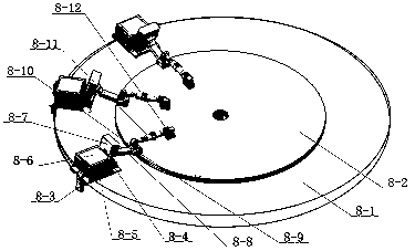
[0024] The intelligent clamping device includes a circular base 8-1, and the edge and surface of the circular base 8-1 are smooth, and the clamping workpiece 8-2 is placed on the base 8-1, The circular base 8-1 is also provided with at least two smart clamps, the intelligent clamps include a sliding card 8-3, and the sliding card 8-3 is snapped onto the circular base 8-1 edge and can slide on the edge of the circular base 8-1, the sliding card 8-3 is fixedly connected with the substrate 8-4 of the smart fixture, and the substrate 8-4 is on the Driven by the slide card 8-3, it can slide on the surface of the circular base 8-1, and the base plate 8-4 is provided with an electrical component 8-5 and a display screen 8-6. The electrical assembly 8-5 is connected with an electric drive box 8-7, and the electric drive box 8-7 is connected with a first electric drive rod 8-8, and the first electric drive rod 8-8 is The end is connected with a first pressure head 8-9, and the first e...
Embodiment approach 3
[0030]This embodiment is a further combination of the first and second embodiments. Disclosed is a multi-functional plate punching mechanism, the multi-functional plate punching mechanism includes a base 1, the base 1 is provided with several support strips 2, the first support strip and the second support strip Two support strips are placed at intervals and form a slideway, the inner side of the edge of the other side of the base 1 relative to the slideway forms a slideway, the first and second slideboards 3 and the slideway respectively Slidingly matched with the chute, the two slides 3 are provided with a bracket 4, one side and / or the other side of the bracket 4 is provided with a drive motor 5, and the bracket 4 is slidably set There is a punching motor 6, the bottom of the punching motor 6 is detachably provided with a punching needle 7, and a clamping device 8 is placed on the base 1, and the clamping device 8 is a smart clip Holding device, the front and rear sides of...
PUM
 Abstract
Description
Claims
Application Information
 - R&D
- Intellectual Property
- Life Sciences
- Materials
- Tech Scout
- Unparalleled Data Quality
- Higher Quality Content
- 60% Fewer Hallucinations
Browse by: Latest US Patents, China's latest patents, Technical Efficacy Thesaurus, Application Domain, Technology Topic, Popular Technical Reports.
© 2025 PatSnap. All rights reserved.Legal|Privacy policy|Modern Slavery Act Transparency Statement|Sitemap|About US| Contact US: help@patsnap.com


