Eureka AIR delivers breakthrough ideas for toughest innovation challenges, trusted by R&D personnel around the world.

A ring die reaming device for feed

A ring die and feed technology, which is used in positioning devices, boring/drilling, drilling/drilling equipment, etc., can solve the problems that the hole is difficult to meet the requirements, the human hand is unstable, and the operability is poor. The effect of solving the problem of punching, saving labor, and reducing the rate of defective products

Active Publication Date: 2019-07-26
莱阳六和饲料有限公司
View PDF6 Cites 0 Cited by
  • Summary
  • Abstract
  • Description
  • Claims
  • Application Information

AI Technical Summary

Problems solved by technology

[0002] In the processing and production process of the feed production workshop, the ring die is a device used on the granulator. It is ring-shaped. After the ring die is used for a period of time, the holes will be deformed. In order to prolong the service life of the ring die, it is necessary Drilling the ring die is currently done by hand-held electric drills. One worker is required to hold the ring die while another worker drills the holes. Since the ring die is made of rigid material, it weighs a lot and cannot be held firmly by hand. , the phenomenon of oblique holes and crooked holes often occurs. Even after the workers hold the ring die more stably, because it is ring-shaped, it needs to punch holes on the arc surface. The operability is poor, and the holes punched out are difficult to meet the requirements.

Method used


Image

  • A ring die reaming device for feed
  • A ring die reaming device for feed
  • A ring die reaming device for feed

Examples


Embodiment 1

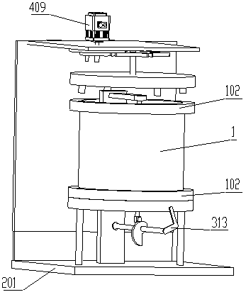
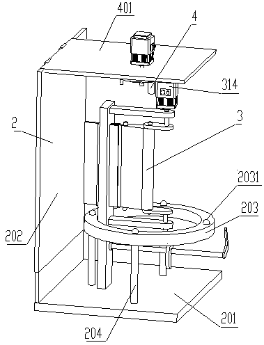
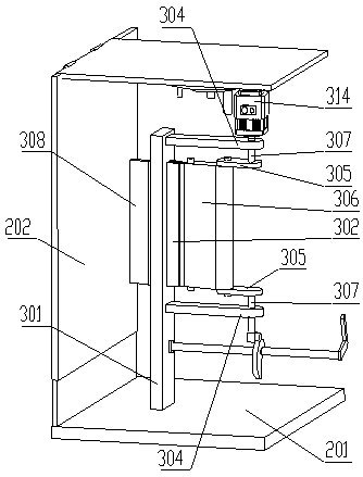
[0046] see Figure 1 to Figure 8 , the present invention provides a ring die reaming device for feed, comprising a ring die 1, a fixing mechanism 2 of the ring die 1, a drilling mechanism 3 arranged on the fixing mechanism 2 and a ring die 1 mounted on the top of the fixing mechanism 2 Turning mechanism 4;

[0047]The ring die 1 comprises a ring die body and ring die retaining rings 102 arranged at both ends of the ring die body, the ring die retaining ring 102 is provided with evenly distributed ring die retaining holes 103, and the ring die 1 body is provided with several through holes; The mechanism 2 includes a fixed base 201, and one side of the fixed base 201 is vertically provided with a telescopic support plate 202; the axial direction of the ring mold is perpendicular to the fixed base 201 and placed on the fixed mechanism 2;

[0048] Drilling mechanism 3 comprises and is fixed on the fixed base 201, and the drilling limit plate 301 perpendicular to the fixed base 20...

Embodiment 2

[0073] On the basis of Embodiment 1, different from Embodiment 1, the displacement mechanism also includes a connection block 309 arranged on one side of the linkage mechanism fixing rod 304, and the connection block 309 is fixedly arranged on the side away from the drilling limit plate 301 There is a roller 310 perpendicular to the surface, a nautilus cam 311 is arranged on the underside of the roller 310, the wheel surface of the roller 310 is attached to the cam surface of the nautilus cam 311, and the cam rotation shaft 312 is set through on the nautilus cam 311;

[0074] One end of the cam rotating shaft 312 is hinged to the drilling limit plate 301 , and a rocking handle 313 is provided at the end of the other end.

[0075] When working, each displacement of the needle drill of the drilling mechanism 3 is a row of radial single-row through-holes; the first week is counted from one row, which is the first 3 5 7th row of radial single-row through-holes. row; after rotating...


PUM


Abstract

The invention discloses a feed circular mold chambering device, and relates to the field of feed production equipment. According to the technical scheme, the device comprises a circular mold, a fixingmechanism of the circular mold, a drilling mechanism arranged on the fixing mechanism and a rotating mechanism arranged at the top of the fixing mechanism for rotating the circular mold; the circularmold comprises a circular mold body and circular mold fixing rings arranged at the two ends of the circular mold body, evenly-distributed circular mold fixing holes are formed in the circular mold fixing rings, and a plurality of through holes are formed in the circular mold body; the fixing mechanism comprises a fixing base, and a stretchable supporting plate is vertically arranged at one side of the fixing base. The device has the advantages that the device performs vertical reinforcing of the circular mold, and automatic punching can be achieved; by adding a displacement mechanism, the circular mold staggered hole position punching problem is solved, operation safety is improved, the circular mold chambering defective percentage is lowered, and labor force is greatly saved.

Description

technical field [0001] The invention relates to the field of feed production equipment, in particular to a feed ring die hole reaming device. Background technique [0002] In the processing and production process of the feed production workshop, the ring die is a device used on the granulator. It is ring-shaped. After the ring die is used for a period of time, the holes will be deformed. In order to prolong the service life of the ring die, it is necessary Drilling the ring die is currently done by hand-held electric drills. One worker is required to hold the ring die while another worker drills. Since the ring die is made of rigid material, it is heavy and unstable , the phenomenon of oblique holes and crooked holes often occurs. Even after the workers hold the ring die more stably, because it is ring-shaped, it needs to punch holes on the arc surface. The operability is poor, and the holes punched out are difficult to meet the requirements. . Contents of the invention ...

Claims


Application Information

Patent Timeline
Patent Type & Authority Patents(China)
IPC IPC(8): B23B41/00B23B47/00B23Q3/06
CPCB23B41/00B23B47/00B23Q3/062
Inventor 王传义张小向邢海鹏夏益民蔡雪梅姜树财刘建民黄美芹
Owner 莱阳六和饲料有限公司
Why Eureka
Eureka Blog
Learn More