
Novel movable discharging mechanism

An unloading mechanism and a new type of technology, applied in the directions of loading/unloading, transportation and packaging, can solve the problems of guiding to both sides of the stopper and the low utilization rate of the effective volume of the silo, so as to achieve clean scraping and avoid material The effect of leak detection and avoidance of material leakage

Pending Publication Date: 2018-05-18
江门市振达机械制造有限公司
View PDF0 Cites 0 Cited by
  • Summary
  • Abstract
  • Description
  • Claims
  • Application Information

AI Technical Summary

Problems solved by technology

[0002] Belt conveyors are widely used in the transportation of materials in industrial and agricultural production. The existing technology is that the belt conveyor transports the materials to the upper part of the silo, and the stopper installed on the conveyor belt blocks the materials, and discharges the materials to the bottom of the unloading device. The problem of the silo is that the materials in the silo are piled up in a conical shape under the unloading device, not only the effective volume utilization rate of the silo is low, but also, because the conveyor belt is a flexible structure, the transverse section is curved during operation. The bulk material on the belt cannot be completely guided to both sides of the material stop by the stopper on the belt, causing the material to move forward with the conveyor belt, and to scatter and accumulate at the return point at the end of the conveyor belt

Method used


Image

  • Novel movable discharging mechanism
  • Novel movable discharging mechanism
  • Novel movable discharging mechanism

Examples


Embodiment Construction

[0019] Embodiments of the present invention are described in detail below, examples of which are shown in the drawings, wherein the same or similar reference numerals designate the same or similar elements or elements having the same or similar functions throughout. The embodiments described below by referring to the figures are exemplary and are intended to explain the present invention and should not be construed as limiting the present invention.

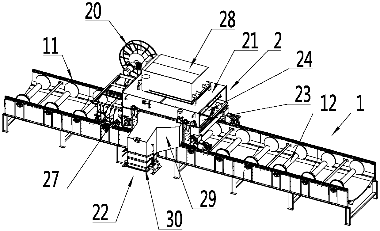
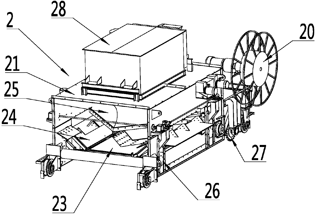
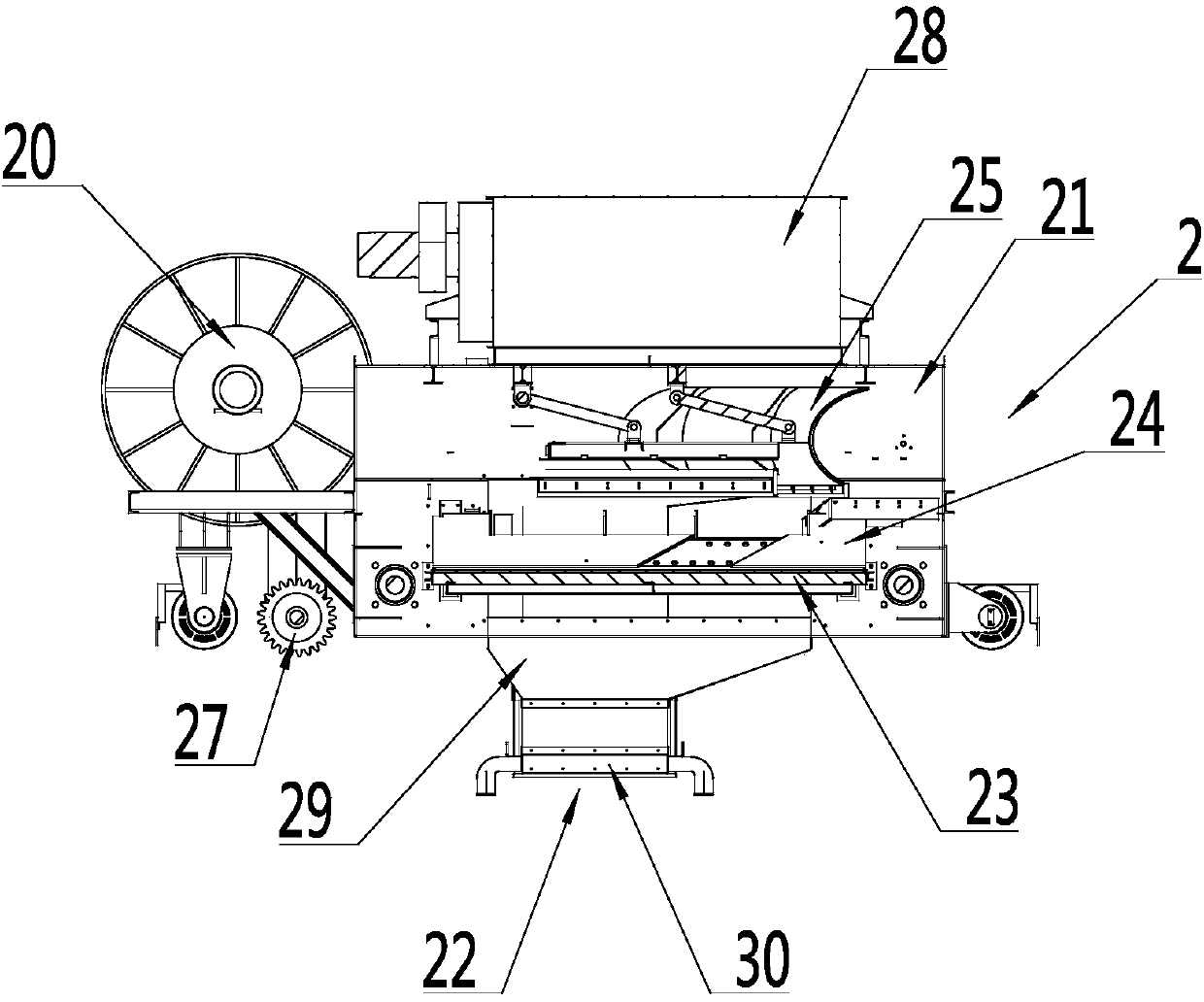
[0020] refer to Figure 1 to Figure 3 , a new type of mobile unloading mechanism, including a roller 12 transmission device 1, and a discharge device 2 movably arranged on the roller 12 transmission device 1, the idler 12 transmission device 1 includes a slide rail 11, a plurality of settings The idler 12 on the slide rail 11, and the conveyer belt surrounding the idler 12 in turn, the unloading device 2 includes a gantry frame 21 that is movably arranged on the slide rail 11, and a gantry frame 21 installed on the side of the ga...


PUM


Abstract

The invention discloses a novel movable discharging mechanism. The novel movable discharging mechanism comprises a carrier roller conveying device and a discharging device which can be movably arranged on the carrier roller conveying device, wherein the carrier roller conveying device comprises sliding rails, a plurality of carrier rollers arranged on the sliding rails and a conveying belt which sequentially surrounds the carrier rollers, and the discharging device comprises a gantry machine frame which can be movably arranged on the sliding rails and a discharging connector which is arrangedon the side part of the gantry machine frame and is used for guiding materials from the gantry machine frame to a warehouse; and a discharging control mechanism which is used for supporting the conveying belt is arranged at the bottom of the gantry machine frame, the discharging control mechanism comprises a supporting plate arranged below the conveying belt and a material distributing device which is arranged above the conveying belt, capable of lifting and used for guiding the materials on the conveying belt into the discharging connector, and material blocking plates capable of rotating relative to the supporting plate are arranged on the two sides of the supporting plate. The novel movable discharging mechanism has the advantages that feeding is uniform, material scraping is clean andmaterial leakage is prevented.

Description

technical field [0001] The invention relates to the field of material conveying equipment, in particular to a novel mobile unloading mechanism. Background technique [0002] Belt conveyors are widely used in the transportation of materials in industrial and agricultural production. The existing technology is that the belt conveyor transports the materials to the upper part of the silo, and the stopper installed on the conveyor belt blocks the materials, and discharges the materials to the bottom of the unloading device. The problem of the silo is that the materials in the silo are piled up in a conical shape under the unloading device, not only the effective volume utilization rate of the silo is low, but also, because the conveyor belt is a flexible structure, the transverse section is curved during operation. The bulk material on the belt cannot be completely guided to both sides of the stopper by the stopper on the belt, causing the material to move forward with the conve...

Claims


Application Information

Patent Timeline
Patent Type & Authority Applications(China)
IPC IPC(8): B65G65/06B65G65/02
CPCB65G65/02B65G65/06
Inventor 李孔成李益波陈宏伟莫之平方梦庚谢汉章饶智敏郑始才宁炳澍伍有照吴向宇
Owner 江门市振达机械制造有限公司
Learn More