Grain drying device

A technology of grain drying and drying box, which is applied to grain drying, drying, dryer and other directions, can solve problems such as low drying efficiency, and achieve the effects of high drying efficiency, prevention of grain leakage detection, and convenient use.

Inactive Publication Date: 2020-12-25
ANHUI GUFENG MECHANICAL TECH CO LTD
View PDF9 Cites 0 Cited by
  • Summary
  • Abstract
  • Description
  • Claims
  • Application Information

AI Technical Summary

Problems solved by technology

[0002] After the grain is harvested, it usually needs to be dried in the sun to remove its own moisture to facilitate storage. The conventional method is to use sunlight to dry, which requires the cooperation of the weather, and the drying efficiency is low

Method used


Image

  • Grain drying device
  • Grain drying device
  • Grain drying device

Examples


Embodiment 1

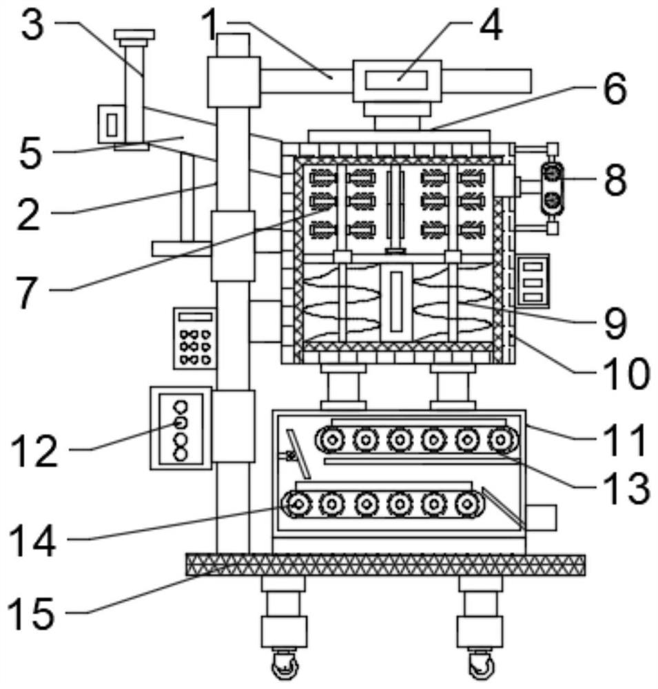
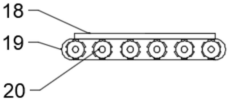
[0022] see Figure 1~4 , in an embodiment of the present invention, a grain drying device includes a mounting frame 2; a top seat 1 is installed on the top of the mounting frame 2; a fixing seat 4 is provided on the top seat 1; The bottom end is connected to the top of the drive mechanism by a hydraulic rod; the bottom end of the drive mechanism is equipped with a stirring paddle 7; the stirring paddle 7 is arranged inside the stirring box 10; Heating layer; the corresponding heating layer on the stirring box 10 is provided with an electronic heater; the bottom of the stirring box 10 is connected to the drying box 11; the inside of the drying box 11 is provided with a transmission drying mechanism; the drying The bottom ends of the box 11 and the installation frame 2 are all installed on the top of the base 15; one side of the stirring box 10 is equipped with a feeding mechanism.

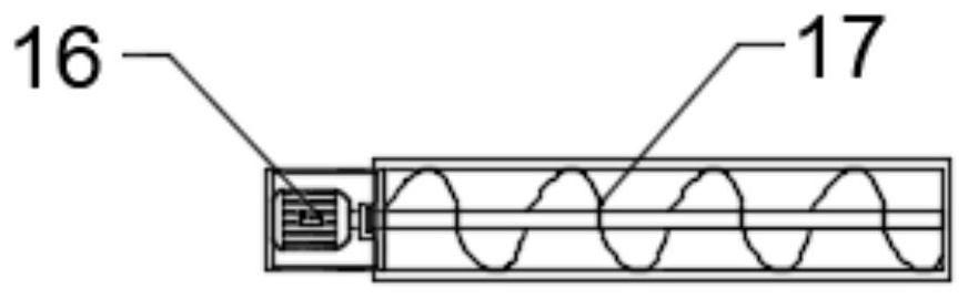
[0023] Further, the feeding mechanism includes a feed pipe 3; the bottom end of the feed pipe 3...

Embodiment 2

[0029] see figure 1 , the bottom of the base 15 is equipped with a moving mechanism; the moving mechanism includes a hydraulic lifting rod; the hydraulic lifting rod is provided with at least four; the bottom of the hydraulic lifting rod is equipped with a lifting box; the lifting box There is a lifting mechanism inside; the bottom end of the lifting mechanism is equipped with a moving wheel; the lifting mechanism can be any type of lifting mechanism in the prior art; through the setting of the lifting mechanism, the moving wheel can be received inside the lifting box , to prevent shaking during drying and affect the efficiency; through the setting of the hydraulic lifting rod, the height of the device can be adjusted, which is convenient to use.

[0030] The working principle of the present invention is: the grain is stirred by the stirring paddle 7, so that the grain is in contact with the heating layer, so that the grain is heated and dried; the height of the stirring paddl...


PUM


Abstract

The invention discloses a grain drying device. The grain drying device comprises a mounting frame; a top seat is mounted at the top end of the mounting frame; a fixing seat is arranged on the top seat; the bottom end of the fixing seat is connected with the top end of a driving mechanism through a hydraulic rod; stirring paddles are mounted at the bottom end of the driving mechanism; the stirringpaddles are arranged in the stirring box; the stirring box is sequentially provided with a heat insulation layer and a heating layer from outside to inside; an electronic heater is arranged on the stirring box corresponding to the heating layer; the bottom end of the stirring box is communicated with the drying box; a transmission drying mechanism is arranged in the drying box; the bottom end of the drying box and the bottom end of the mounting frame are both mounted at the top of the base; and a feeding mechanism is mounted on one side of the stirring box. The grain drying device is convenient to use and high in drying efficiency.

Description

technical field [0001] The invention relates to the technical field of grain drying, in particular to a grain drying device. Background technique [0002] After the grain is harvested, it usually needs to be dried in the sun to remove its own moisture to facilitate storage. The conventional method is to use sunlight to dry, which requires the cooperation of the weather, and the drying efficiency is low. [0003] Therefore, in view of the above present situation, it is urgent to develop a grain drying device. Contents of the invention [0004] The object of the present invention is to provide a grain drying device to solve the problems raised in the above-mentioned background technology. [0005] To achieve the above object, the present invention provides the following technical solutions: [0006] A grain drying device, comprising a mounting frame; a top seat is installed on the top of the mounting frame; a fixing seat is provided on the top seat; the bottom end of the f...

Claims


Application Information

Patent Timeline
Patent Type & Authority Applications(China)
IPC IPC(8): F26B20/00F26B11/14F26B17/04F26B17/12F26B23/00F26B25/00F26B25/02F26B25/04A23B9/08
CPCA23B9/08F26B11/14F26B17/04F26B17/12F26B20/00F26B23/00F26B25/00F26B25/002F26B25/02F26B25/04F26B2200/06
Inventor 刘吉勇许存伍
Owner ANHUI GUFENG MECHANICAL TECH CO LTD
Why Eureka
Try Eureka