cable trench cover bridge

A trench cover slab bridge and cable technology, which is applied in the field of cable trench cover slab bridges, can solve the problems of cable trench cover rigidity damage, steel plates can not realize the bearing function, etc., to improve traffic efficiency, improve the environment and work efficiency, and flexibility high effect

Active Publication Date: 2020-05-26
STATE GRID CORP OF CHINA +2
View PDF10 Cites 0 Cited by
  • Summary
  • Abstract
  • Description
  • Claims
  • Application Information

AI Technical Summary

Problems solved by technology

[0003] However, in the process of substation erection or operation and maintenance, it is necessary to enter heavy vehicles, such as cranes or lift trucks, etc. When heavy vehicles pass by, it will cause rigid damage to the cable trench cover, making the steel plate unable to achieve the original load-bearing role, so how to Designing a device that is convenient for heavy vehicles to move in the substation and can protect the cable trench cover is a technical problem that those skilled in the art need to solve urgently

Method used


Image

  • cable trench cover bridge
  • cable trench cover bridge
  • cable trench cover bridge

Examples


Embodiment 1

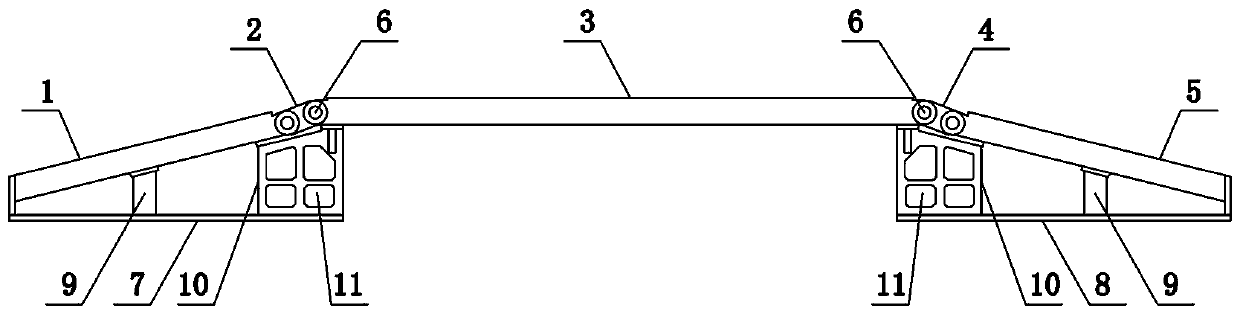
[0029] Such as Figure 1 to Figure 3 As shown, the present invention comprises a left cover plate 1, a left connecting plate 2, an intermediate cover plate 3, a right connecting plate 4 and a right cover plate 5 from left to right, and the two ends of the left connecting plate 2 pass through the rotating shaft 6 and the left cover respectively. The plate 1 and the middle cover 3 are rotationally connected, the two ends of the right connecting plate 4 are respectively hinged 5 with the middle cover 3 and the right cover 5 through the rotating shaft 6, and the lower end of the left cover 1 is provided with a left support 7 and a right cover 5 Right support plate 8 is set on the lower end face of the bottom surface, support column 9 and support frame 10 are all set between left cover plate 1 and left support plate 7, between right cover plate 5 and right support plate 8, and the height of support column 9 is less than support frame The height of 10, the support frame 10 is arrang...

Embodiment 2

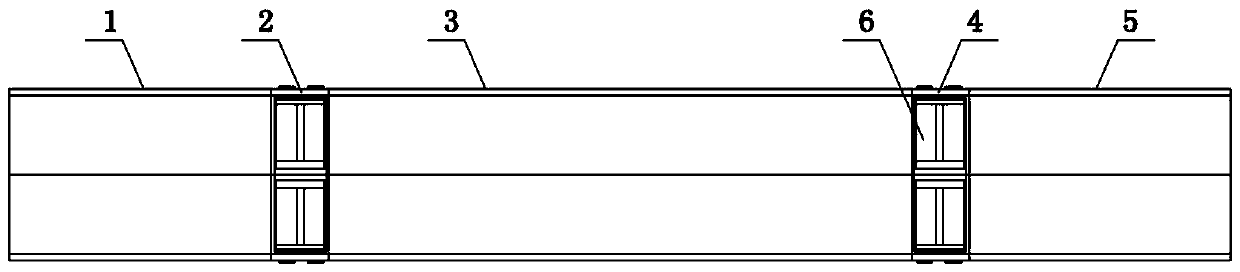
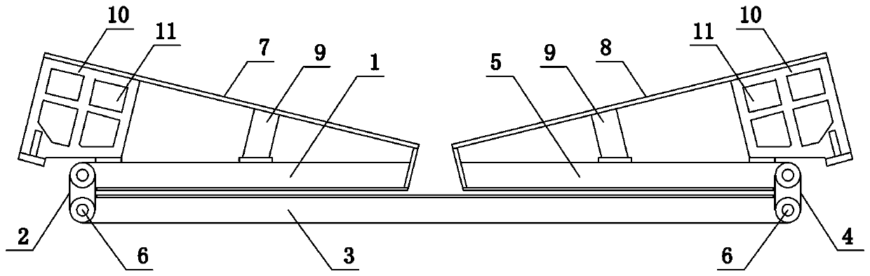
[0031] Such as Figure 4 with Figure 5 As shown, the present invention comprises a left cover plate 1, a left connecting plate 2, an intermediate cover plate 3, a right connecting plate 4 and a right cover plate 5 from left to right, and the two ends of the left connecting plate 2 pass through the rotating shaft 6 and the left cover respectively. The plate 1 and the middle cover 3 are rotationally connected, the two ends of the right connecting plate 4 are respectively hinged 5 with the middle cover 3 and the right cover 5 through the rotating shaft 6, and the lower end of the left cover 1 is provided with a left support 7 and a right cover 5 Right support plate 8 is set on the lower end face of the bottom surface, support column 9 and support frame 10 are all set between left cover plate 1 and left support plate 7, between right cover plate 5 and right support plate 8, and the height of support column 9 is less than support frame The height of 10, the support frame 10 is ar...

Embodiment 3

[0034]The present invention comprises left cover plate 1, left connecting plate 2, middle cover plate 3, right connecting plate 4 and right cover plate 5 successively from left to right, and the two ends of left connecting plate 2 pass rotating shaft 6 and left cover plate 1 and The middle cover plate 3 is rotationally connected, and the two ends of the right connecting plate 4 are respectively hinged 5 with the middle cover plate 3 and the right cover plate through the rotating shaft 6. The right support plate 8 is set, the support column 9 and the support frame 10 are all arranged between the left cover plate 1 and the left support plate 7, between the right cover plate 5 and the right support plate 8, and the height of the support column 9 is less than the height of the support frame 10 , the support frame 10 is arranged close to the middle cover plate 3, the support frame 10 between the left cover plate 1 and the left support plate 7 simultaneously supports the right end of...


PUM


Abstract

The invention belongs to the technical field of electric facilities, and particularly relates to a cable trench cover plate bridge. The cable trench cover plate bridge comprises a left cover plate, aleft connecting plate, a middle cover plate, a right connecting plate and a right cover plate from left to right in sequence, the two ends of the left connecting plate are respectively hinged with theleft cover plate, the two ends of the right connecting plate are respectively hinged with the middle cover plate and the right cover plate, a left supporting plate is arranged at the lower end of theleft cover plate, and a right supporting plate is arranged at the lower end of the right cover plate. The cable trench cover plate bridge provided by the invention provides a temporary channel for vehicles, protects a cable trench, and greatly improves the working environment and the working efficiency in a substation, and the folding structure can be conveniently carried on the vehicle, so thatthe flexibility is high.

Description

technical field [0001] The invention belongs to the technical field of electric power facilities, in particular to a cable trench cover plate bridge. Background technique [0002] In the substation environment, there are many vertical and horizontal cable trenches. The span of the cable trench is usually 0.8m-1.2m, and the depth is about 1.2m, and the cable brackets are installed on both sides of the cable brackets, and the transmission cables are laid on the cable brackets; To solve the problem of falling, a cover plate is laid on the upper end of the cable trench to facilitate manual passage. The cover plate adopts a steel structure or a prefabricated concrete structure. [0003] However, in the process of substation erection or operation and maintenance, it is necessary to enter heavy vehicles, such as cranes or lift trucks, etc. When heavy vehicles pass by, it will cause rigid damage to the cable trench cover, making the steel plate unable to achieve the original load-be...

Claims


Application Information

Patent Timeline
Patent Type & Authority Patents(China)
IPC IPC(8): H02G9/02
CPCH02G9/025
Inventor 李应文彭勇沈辉张露江李璐曲欣许东升张嘉涛胡润阁王来军鄂世平孟异山方强华兰琦牛田野刘富荣王洪涛刘旭贺李辉连伟华黄玉洋李相成李全中
Owner STATE GRID CORP OF CHINA
Why Eureka
Try Eureka