High-speed roaming method of wireless LAN

a wireless lan and high-speed technology, applied in the field of high-speed roaming technology, can solve the problem of consuming time until the subscription

Inactive Publication Date: 2002-02-28
CLARION CO LTD
View PDF1 Cites 148 Cited by
  • Summary
  • Abstract
  • Description
  • Claims
  • Application Information

AI Technical Summary

Problems solved by technology

As a result, there is the problem such that the time is consumed until the subscription operation.

Method used


Image

  • High-speed roaming method of wireless LAN
  • High-speed roaming method of wireless LAN
  • High-speed roaming method of wireless LAN

Examples


Embodiment Construction

[0031] Embodiments of the present invention will be explained in detail with reference to the accompanying drawings hereinafter.

Structural Example of the Wireless LAN

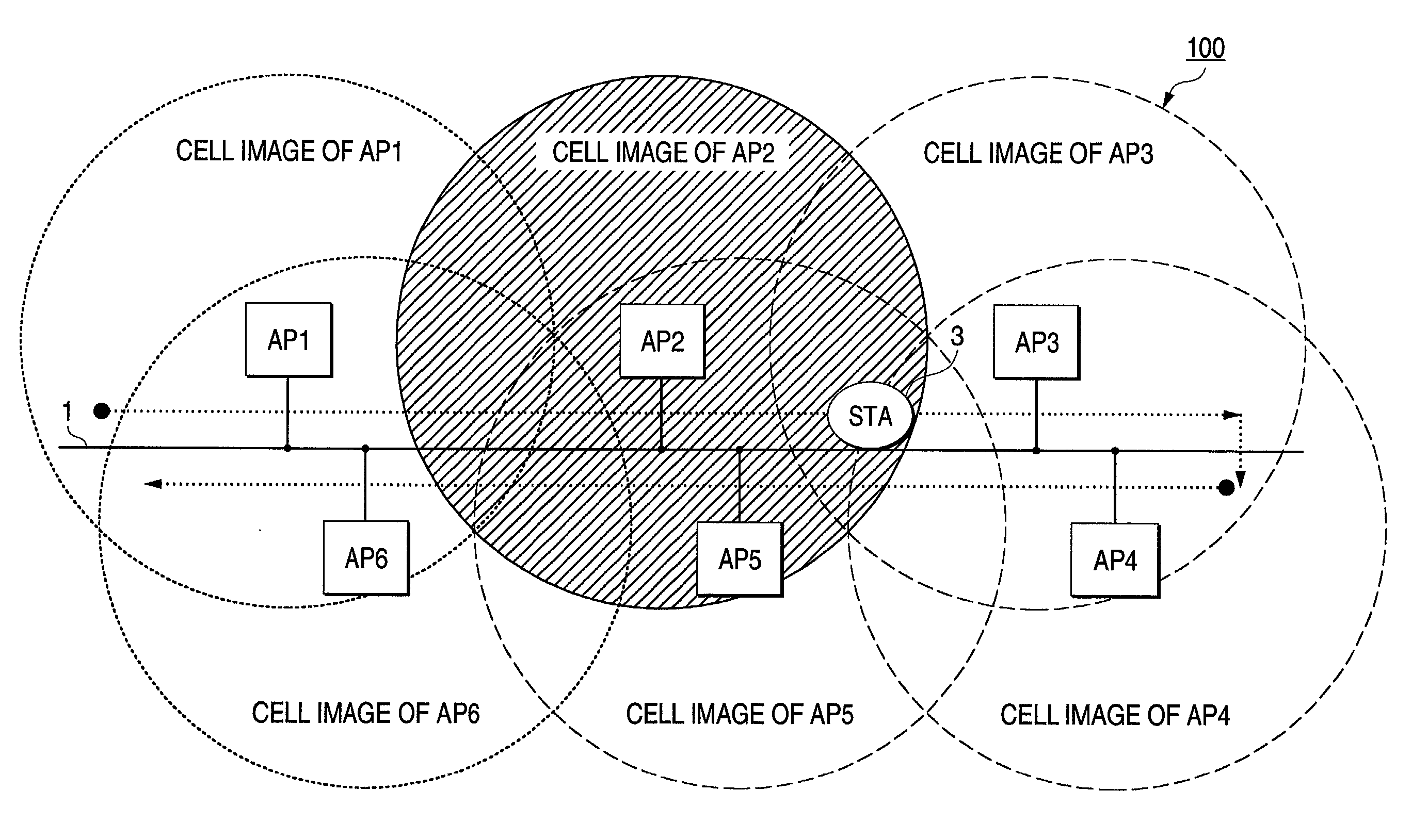
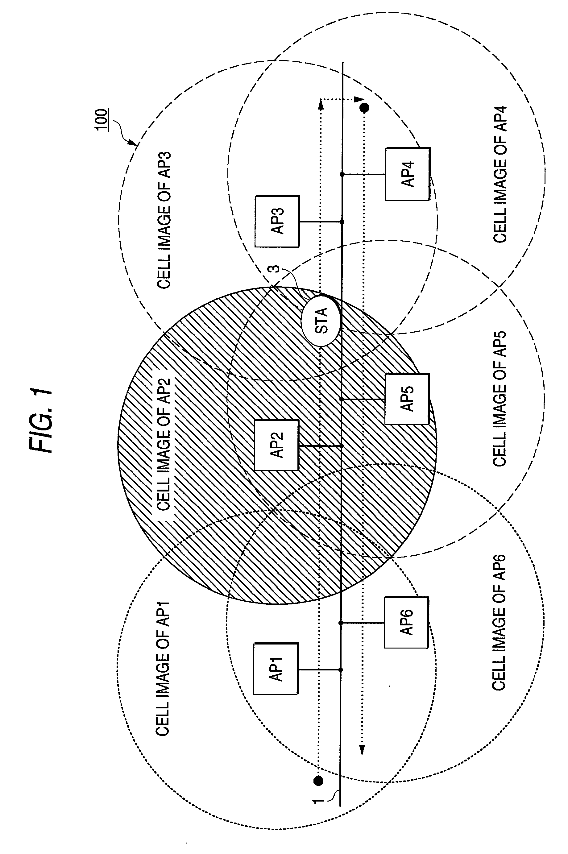
[0032] FIG.1 is a schematic view showing an embodiment of a wireless LAN to which a high-speed roaming method of the present invention can be applied. In FIG.1, an Ethernet 1, a plurality of access points AP1, AP2, . . . , AP6 provided in the Ethernet 1, and a station 3 that moves in the direction indicated by an arrow are shown as a wireless LAN 100 (One mobile station is shown in FIG.1 but such station is not limited to this. A plurality of mobile stations may be employed).

[0033] Also, respective access points function as one type bridge between the Ethernet 1 and the station 3. Each access point receives the frame that is directed to the MAC (Media Access Control) address of the subsidiary station 3 from the IEEE802.3 (reference specification) frame transmitted from the backbone Ethernet, then converts such frame int...


PUM


Abstract

All access points are operated synchronously, and monitor the beacon to mate with the hopping frequency of the neighboring access point. Accordingly, the station can grasp the up-to-date radio situation of the neighboring access point to be entered subsequently, and constructs the information as the database. As a result, when the beacon quality of the current subscription (connected) access point is reduced lower than the threshold value, the hopping channel and the hopping pattern are fitted to the neighboring access point having the best communication environment by referring the database, and then the subscription operation is applied directly.

Description

[0001] 1. Technical Field of the Invention[0002] The present invention relates to a high-speed roaming technology in the infrastructure type wireless LAN environment.[0003] 2. Related Art[0004] Initially LAN (Local Area Network) is developed and utilized as the wire network. In recent years, the wireless LAN is developed and utilized in cooperation with the high communication speed and the progress of the mobile computing technology and the mobile terminal.[0005] The wireless LAN is such a network system that a part of the wire LAN is constructed by the wireless system to incorporate the station into the LAN, and in many cases the Ethernet is employed as the wire LAN.[0006] In this case, the station is normally the general term of PC having the FH-WLAN (Frequency Hopping-Wireless LAN) adaptor, and means the notebook PC into which the FH-WLAN card is inserted, the desktop PC which has the FH-WLAN.cndot.ISA (Industrial Reference Architecture) adaptor, or the like. In case the wireless...

Claims


Application Information

Patent Timeline
Patent Type & Authority Applications(United States)
IPC IPC(8): H04L12/28H04W48/12H04W48/20
CPCH04W48/12H04W48/20H04W48/16
Inventor TAKAYAMA, TAKASHISATO, KIYOTAKA
Owner CLARION CO LTD
Why Eureka
Try Eureka