Stimulator and method of controlling stimulator

A technology of stimulators and stimulation signals, which is applied in cardiac stimulators, electrotherapy, artificial respiration, etc., and can solve problems such as the reduction of power efficiency of stimulators

Active Publication Date: 2018-05-25
SAMSUNG ELECTRONICS CO LTD
View PDF8 Cites 1 Cited by
  • Summary
  • Abstract
  • Description
  • Claims
  • Application Information

AI Technical Summary

Problems solved by technology

Reduced power efficiency of the stimulator when the operating voltage of the

Method used


Image

  • Stimulator and method of controlling stimulator
  • Stimulator and method of controlling stimulator
  • Stimulator and method of controlling stimulator

Examples


Embodiment Construction

[0045] The following detailed description is provided to assist the reader in gaining an overall understanding of the methods, devices and / or systems described herein. However, various changes, modifications, and equivalents of the methods, devices, and / or systems described herein will be apparent after gaining a thorough understanding of the disclosure of the present application. For example, the order of operations described herein are examples only, are not limited to the order set forth herein, and, except for operations that must occur in a particular order, may be changed as clearly after understanding the disclosure of the present application. Also, descriptions of features that are known in the art may be omitted for increased clarity and conciseness.

[0046] The features described herein can be implemented in different forms and should not be construed as limited to the examples described here. Rather, the examples described herein have been provided merely to illus...


PUM


Abstract

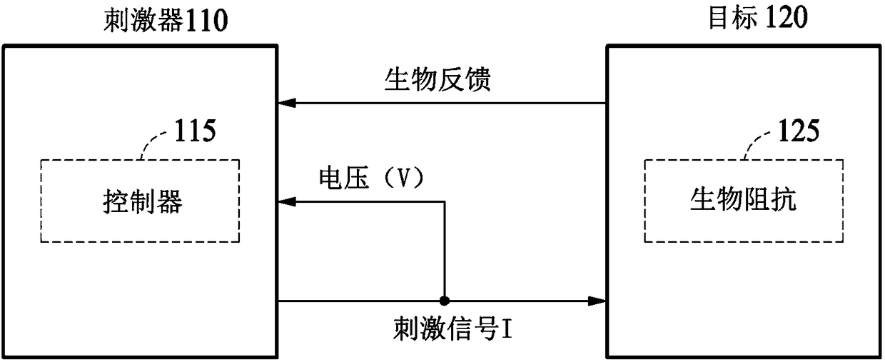
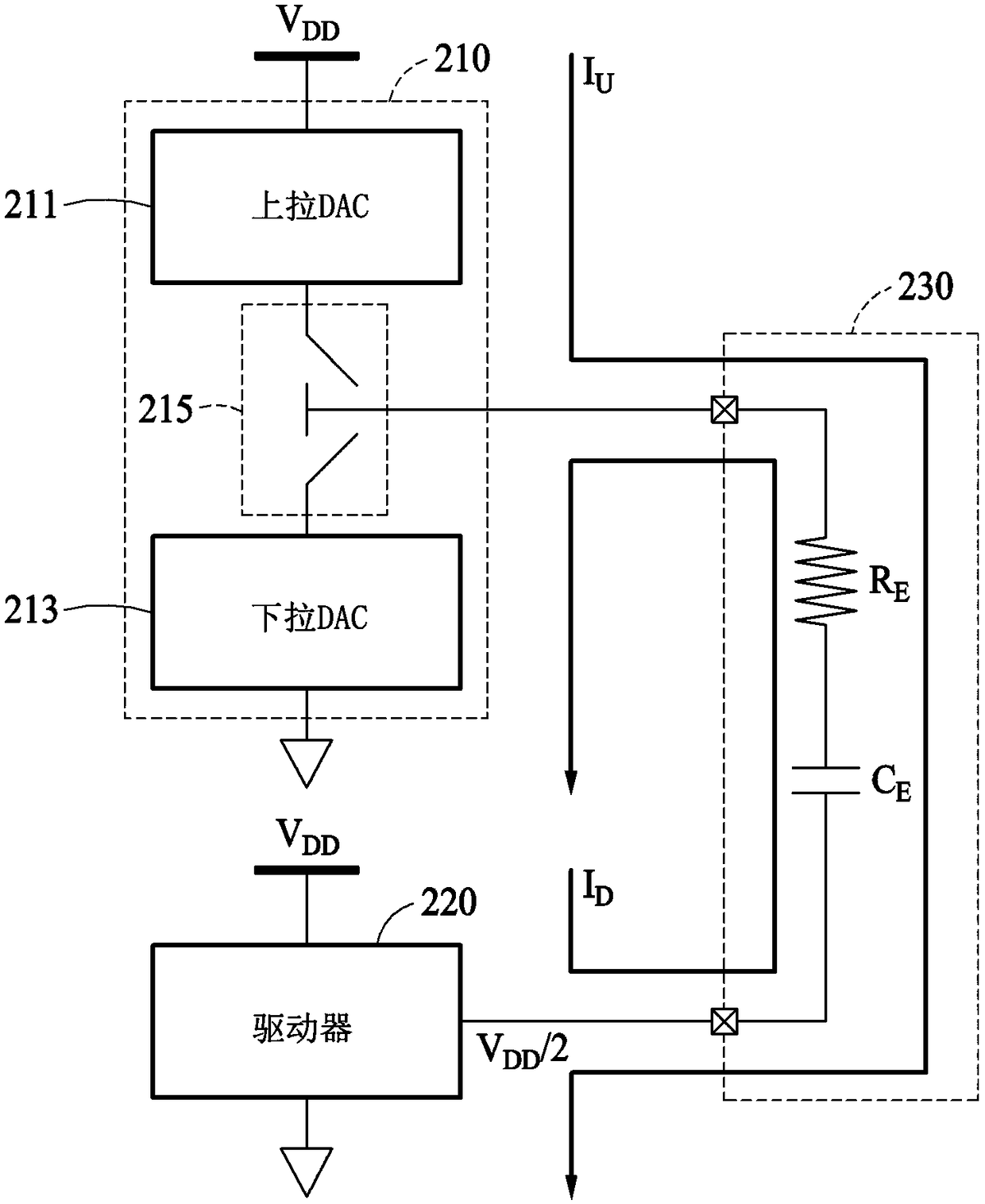
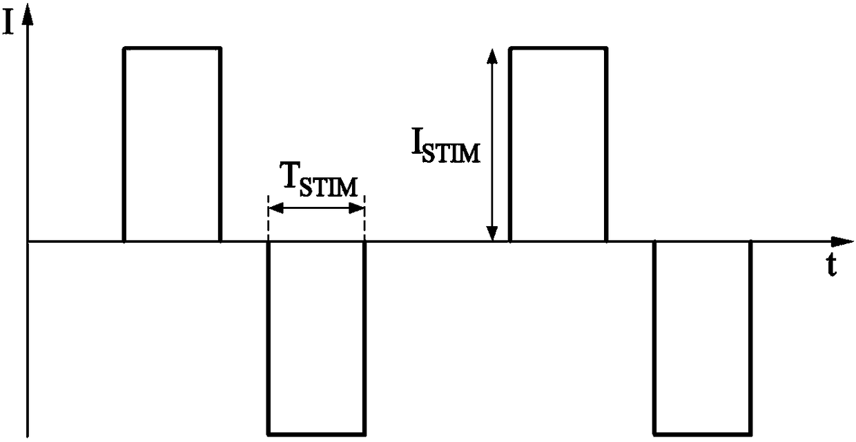
A stimulator and a method of controlling the stimulator are provided. The method includes determining a waveform of a stimulus signal for a target, based on biological feedback of the target responding to a first stimulus signal, calculating bioimpedance of the target based on a voltage waveform measured by applying the stimulus signal with the determined waveform to the target, and determining anoperating voltage of the stimulator based on the determined waveform and the calculated bioimpedance.

Description

[0001] This application claims Korean Patent Application No. 10-2016-0152419 filed with the Korean Intellectual Property Office on November 16, 2016 and Korean Patent Application No. 10-2017-0099744 filed with the Korean Intellectual Property Office on August 7, 2017 Interest in Patent Application, the entire disclosure of which is hereby incorporated by reference for all purposes. technical field [0002] The following description relates to a stimulator and a method of controlling the stimulator. Background technique [0003] Stimulators apply electrical stimulation to body parts such as the brain, heart or muscles. Based on the body part's response to the electrical stimulation, therapy, rehabilitation or cosmetic treatment can be performed. In an example, the stimulator applies electrical stimulation of an appropriate intensity to the paralyzed muscle to restore function to the paralyzed muscle. The stimulator applies current to the body part in a preset waveform based...

Claims


Application Information

Patent Timeline
IPC IPC(8): A61N1/36A61N1/32A61N1/02
CPCA61N1/02A61N1/328A61N1/36003A61N1/36017A61N1/36025A61N1/362A61N1/378A61N1/0529A61N1/0551A61N1/36A61N1/0456A61N1/32A61N1/04A61N1/05
Inventor 李亨优金钟汃郑丞哲
Owner SAMSUNG ELECTRONICS CO LTD
Why Eureka
Try Eureka