Pneumatic clamping jaw

A technology of pneumatic grippers and clamping claws, which is applied in the mechanical field, can solve the problems of inconvenient workpiece grasping operation, inconvenient telescopic operation, rotation operation, position movement, and less degrees of freedom, and achieve reasonable structural design, easy operation, The effect of improving guidance performance

Inactive Publication Date: 2018-05-25
TONGCHENG LIQIONG METAL PROD
View PDF6 Cites 18 Cited by
  • Summary
  • Abstract
  • Description
  • Claims
  • Application Information

AI Technical Summary

Problems solved by technology

[0002] The current pneumatic grippers have fewer degrees of freedom during use, and it is inconvenient to perform telescopic operations, rotation operations, and positional movements, which is inconvenient for the gripping operation of workpieces.

Method used


Image

  • Pneumatic clamping jaw

Examples


Embodiment Construction

[0013] In order to make the object, technical solution and advantages of the present invention clearer, the present invention will be further described in detail below in conjunction with the accompanying drawings and embodiments. It should be understood that the specific embodiments described here are only used to explain the present invention, not to limit the present invention.

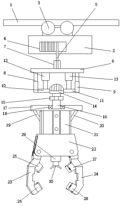
[0014] see figure 1 , the pneumatic gripper includes a sliding track 1, an electric hoist 2 installed on the sliding track 1, a rotating rod 4 is installed on the electric hoist 2, and a ring is processed on the rotating rod 4 groove, and a steel wire 5 is wound on the rotating rod 4, one end of the steel wire 5 is used to connect the hook 7 installed on the support top plate 6, and a first guide is installed on the bottom end side of the support top plate 6 Telescopic rod 8, the second guide telescopic rod 9 is installed on the other side of the bottom end of described support top plate 6, and th...


PUM


Abstract

The invention discloses a pneumatic clamping jaw. The pneumatic clamping jaw comprises a slide rail, an electric hoist, a rotary rod, a steel wire, a hook, a first guide telescopic rod, a second guidetelescopic rod, a first supporting square rod, a second supporting square rod, a first driver, a second driver, a motor, a rotary shaft, a rotary plate, a first supporting rod body, a second supporting rod body and an air cylinder. A clamping seat body is installed at the lower end of the air cylinder, a first clamping jaw body is movably installed in the clamping seat body, a second clamping jawbody is movably installed in the clamping seat body, and an air cylinder rod of the air cylinder drives the first clamping jaw body and the second clamping jaw body to move; a first L-shaped clampingblock and a second L-shaped clamping block are fixedly installed on the clamping wall face of the first clamping jaw body through bolts, and a third L-shaped clamping block and a fourth L-shaped clamping block are fixedly installed on the clamping wall face of the second clamping jaw body through bolts; and a driver is fixedly installed at the lower end of the clamping seat body, and an arc-shaped clamping block is installed at the bottom end of the driver.

Description

technical field [0001] The invention relates to the field of mechanical technology, in particular to a pneumatic gripper. Background technique [0002] During the use of the current pneumatic gripper, there are few degrees of freedom, and it is not convenient to perform telescopic operation, rotation operation and positional movement, so it is not convenient to perform the grasping operation of the workpiece. Contents of the invention [0003] In order to overcome the deficiencies in the prior art, the present invention provides a pneumatic gripper. [0004] The present invention is realized through the following technical solutions: [0005] A pneumatic gripper, comprising a sliding track, an electric hoist installed on the sliding track, a rotating rod is installed on the electric hoist, an annular groove is processed on the rotating rod, and the rotating rod is wound on the rotating rod There is a steel wire, one end of the steel wire is used to connect the hook insta...

Claims


Application Information

Patent Timeline
Patent Type & Authority Applications(China)
IPC IPC(8): B25J5/02B25J9/10B25J15/08
Inventor 程琼明
Owner TONGCHENG LIQIONG METAL PROD
Why Eureka
Try Eureka