Lifting device for cylinder cover of biological tissue dehydrator

A technology of biological tissue and lifting device, which is applied in the preparation of test samples and other directions, can solve the problems of poor stability, inconvenient control of cylinder head lifting, inability to manually control cylinder head lifting, etc., and achieve the effect of easy lifting

Inactive Publication Date: 2019-01-29
湖北海昂电子科技有限公司
View PDF1 Cites 3 Cited by
  • Summary
  • Abstract
  • Description
  • Claims
  • Application Information

AI Technical Summary

Problems solved by technology

[0005] Aiming at the above-mentioned shortcomings existing in the prior art, the present invention provides a cylinder head lifting device for a biological tissue dehydrator, which can effectively overcome the problems in the prior art of complex structure, poor stability, and difficulty in controlling the lifting of the cylinder head. It also solves the problem that the lifting of the cylinder head cannot be manually controlled when the power is off

Method used


Image

  • Lifting device for cylinder cover of biological tissue dehydrator
  • Lifting device for cylinder cover of biological tissue dehydrator

Examples


Embodiment

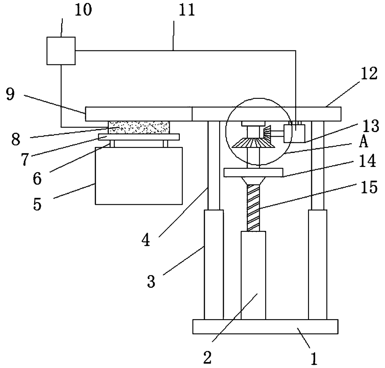
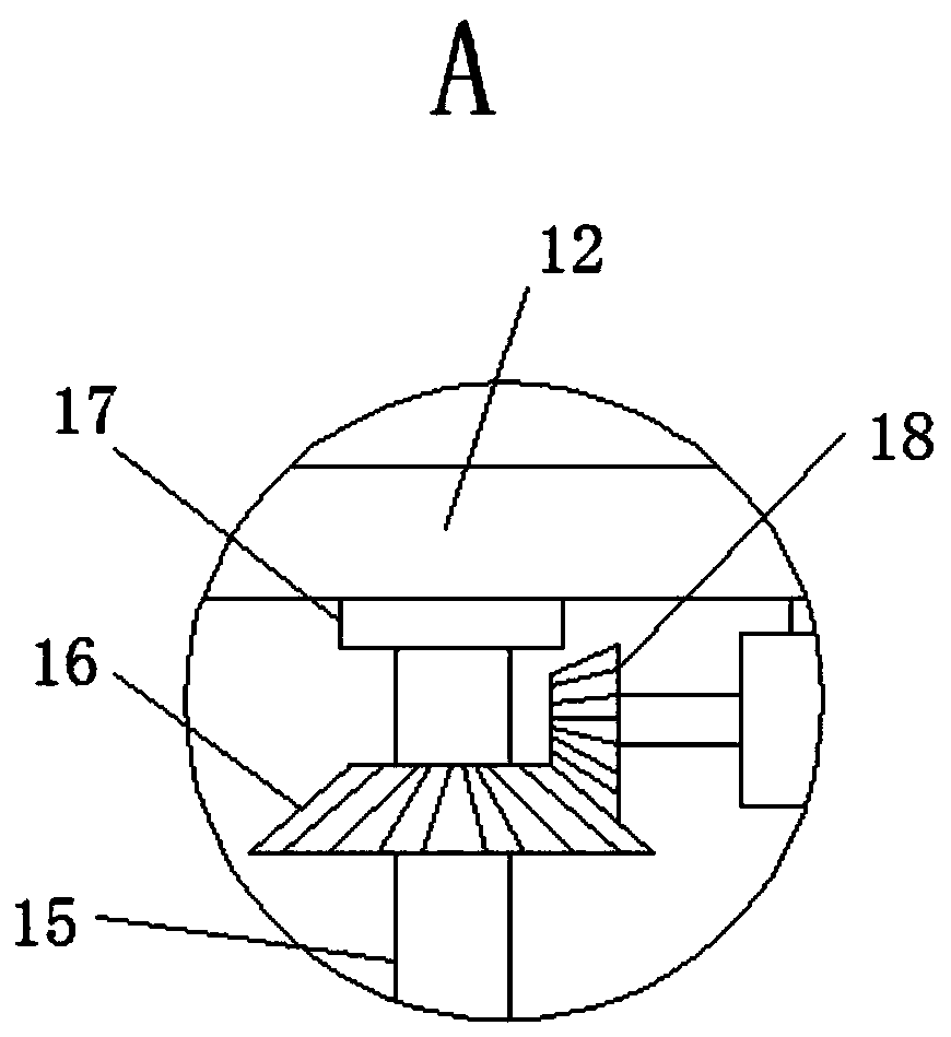
[0024] Depend on Figure 1 ~ Figure 2 It can be seen that a cylinder head lifting device for a biological tissue dehydrator of the present invention includes a base 1, which is characterized in that a helical sleeve 2 and a guide sleeve 3 are fixed on the upper surface of the base 1, and the inner wall of the helical sleeve 2 is threadedly connected with a screw rod 15 , the outer wall of the screw 15 is fixed with a hand wheel 14 and a driven bevel gear 16, and the driven bevel gear 16 is meshed with a driving bevel gear 18, and the driven bevel gear 16 is fixed on the output shaft of the drive motor 13, and the screw 15 The top of the shaft sleeve 17 is provided with a shaft sleeve 17, and the top of the shaft sleeve 17 is fixed with a support plate 12; the left end of the support plate 12 is fixed with a boom 9, the lower surface of the boom 9 is inlaid with an electromagnet 8, and the lower end of the electromagnet 8 is magnetically attracted. Cylinder head 7, the lower su...


PUM


Abstract

The invention relates to the technical field of biological tissue dehydrators, in particular to a lifting device for a cylinder cover of a biological tissue dehydrator, which includes a base. A spiralsleeve and a guiding sleeve are fixed on the upper surface of the base. A screw is threadably connected to the inner wall of the spiral sleeve. A hand wheel and a driven bevel gear are fixed on the outer wall of the screw. The driven bevel gear is externally meshed with a driving bevel gear. The driven bevel gear is fixed to an output shaft of a driving motor. A sleeve is provided on the top endof the screw. A support plate is fixed on the top end of the sleeve. A lifting arm is fixed on the left end of the support plate. The lower surface of the lifting arm is embedded with an electromagnet. The cylinder cover is magnetically attracted to the lower end of the electromagnet. A hook is fixed on the lower surface of the cylinder cover. A nacelle is hooked on the lower end of the hook. Thelifting device for the cylinder cover of the biological tissue dehydrator solves the problems of complicated structure, poor stability, inconvenience in controlling the lifting and the lowering of thecylinder cover, and also solves the problem that the cylinder cover cannot be manually controlled when the power is cut off.

Description

technical field [0001] The invention relates to the technical field of a biological tissue dehydrator, in particular to a lifting device for a cylinder head of a biological tissue dehydrator. Background technique [0002] The biological tissue dehydrator includes a boom and a hanging basket, and the boom is connected to the hanging basket; the biological tissue to be processed is placed in the hanging basket, and under the control of the control device according to the set program, the hanging basket is suspended by the boom. On the running track, the hanging baskets are gradually placed into various soaking tanks filled with various soaking liquids and paraffin for soaking dehydration and embedding paraffin, until the dehydration process of the entire biological tissue is completed; in order to prevent soaking tanks The liquid volatilizes, the top of the hanging basket is provided with a cylinder cover, the boom is connected with the upper part of the cylinder cover, the up...

Claims


Application Information

Patent Timeline
Patent Type & Authority Applications(China)
IPC IPC(8): G01N1/28
CPCG01N1/31
Inventor 李艾华
Owner 湖北海昂电子科技有限公司
Why Eureka
Try Eureka