Projection player, playing method thereof and computer storage medium
The technology of a playback device and a playback method, which is applied in the direction of using projection device image reproducers, color TV parts, electrical components, etc., can solve the problems of viewing image distortion and wall unevenness, and achieve the effect of reducing viewing image distortion
Inactive Publication Date: 2018-05-25
BOE TECH GRP CO LTD +1
6 Cites 2 Cited by
AI-Extracted Technical Summary
Problems solved by technology
[0005] In view of this, the primary purpose of the present invention is to provide a projection playback device, a playback method the...
Abstract
The embodiment of the invention provides a projection player, a playing method thereof and a computer storage medium. The playing method comprises the steps of determining a preset standard test imageaccording to the distance between the projection player and a playing projection area, projecting the standard test image to the playing projection area, and obtaining a reflection image of the standard test image after reflection in the playing projection area; comparing the standard test image and the reflection image and determining an abnormal area of the playing projection area; determininga pixel area to be compensated in a to-be-played image, corresponding to the abnormal area; making compensation for input signals corresponding to the pixel area to be compensated according to presetcompensation parameters, and projecting the image after compensation to the playing projection area to be played. Due to compensation for the input signals corresponding to the pixel area to be compensated, image observation distortion caused by rough and uneven surface of the playing projection area can be reduced.
Application Domain
Picture reproducers using projection devices
Technology Topic
DistortionComputer vision +3
Image
Examples
- Experimental program(1)
Example Embodiment
[0048] The following describes in detail the embodiments of the present invention, examples of which are illustrated in the accompanying drawings, wherein the same or similar reference numerals refer to the same or similar elements or elements having the same or similar functions throughout. The embodiments described below with reference to the accompanying drawings are exemplary and are only used to explain the present invention, but not to be construed as a limitation of the present invention.
[0049] It will be understood by those skilled in the art that the singular forms "a", "an", "the" and "the" as used herein can include the plural forms as well, unless expressly stated otherwise. It should be further understood that the word "comprising" used in the description of the present invention refers to the presence of stated features, integers, steps, operations, elements and/or components, but does not exclude the presence or addition of one or more other features, Integers, steps, operations, elements, components and/or groups thereof. It will be understood that when we refer to an element as being "connected" or "coupled" to another element, it can be directly connected or coupled to the other element or intervening elements may also be present. Furthermore, "connected" or "coupled" as used herein may include wirelessly connected or wirelessly coupled. As used herein, the term "and/or" includes all or any element and all combination of one or more of the associated listed items.
[0050] It will be understood by those skilled in the art that, unless otherwise defined, all terms (including technical and scientific terms) used herein have the same meaning as commonly understood by one of ordinary skill in the art to which this invention belongs. It should also be understood that terms, such as those defined in a general dictionary, should be understood to have meanings consistent with their meanings in the context of the prior art and, unless specifically defined as herein, should not be interpreted in idealistic or overly formal meaning to explain.
[0051] The inventors of the present invention have studied the prior art and found the following problems.
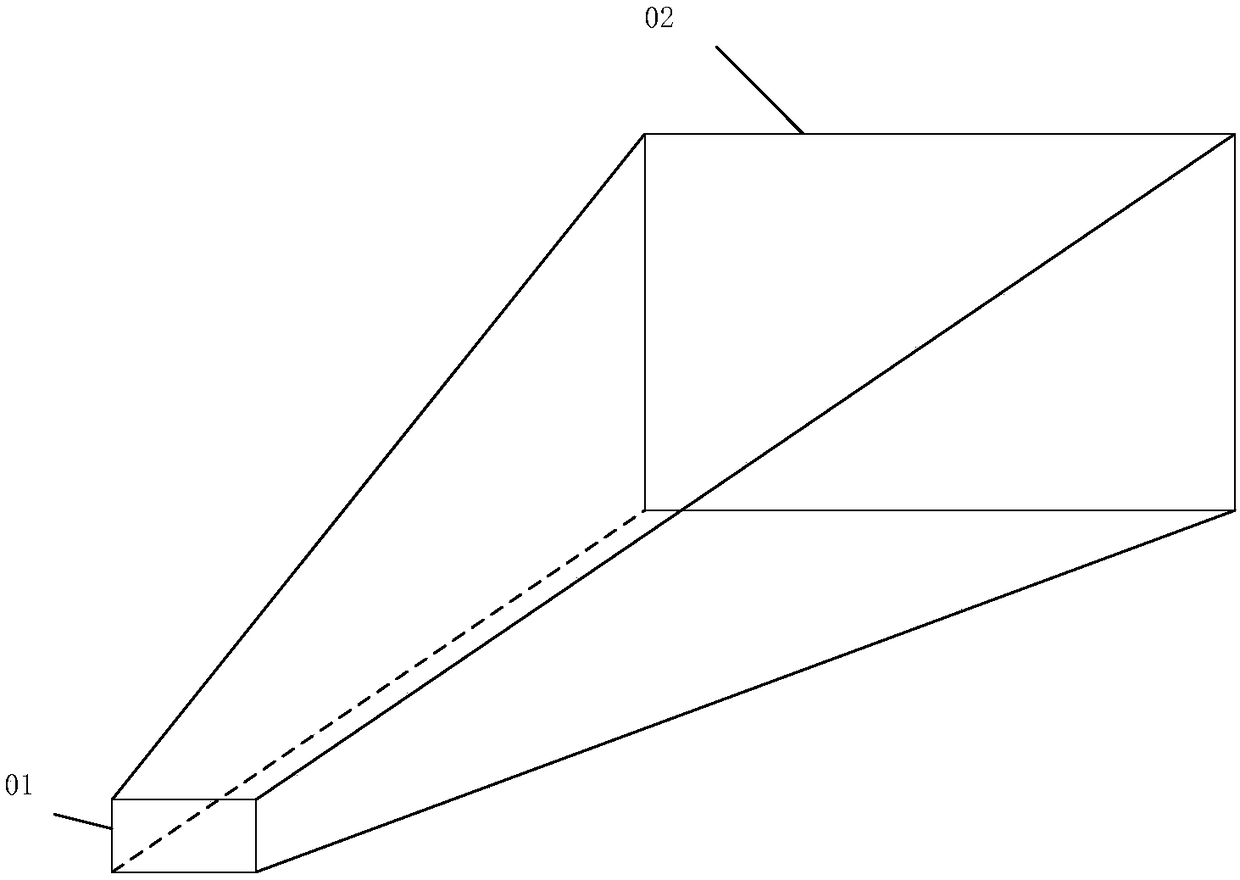
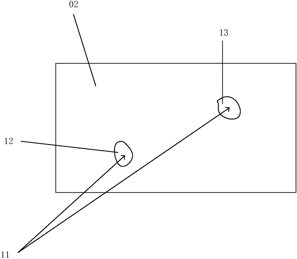
[0052] like figure 1 As shown, the projection playback device 01 projects the image to the projection area 02. Since the surface of the projection area 02 is not smooth, there may be unevenness in some areas, such as figure 2 As shown, there are two uneven abnormal areas in the projection area 02, such as the abnormal area 12 and the abnormal area 13. Here, only two abnormal areas are used as examples for description, and there may be many abnormal areas in actual situations.
[0053] During the research, the inventor found that when the light 11 projected by the projection playback device 01 is projected onto the abnormal area 12 and the abnormal area 13, since the abnormal area 12 and the abnormal area 13 are compared with other areas of the projection area 02, the The reflections of the light rays 11 projected by the projection and playback device 01 are different. Therefore, the reflected images of the abnormal area 12 and the abnormal area 13 will cause image distortion when viewed.
[0054] The technical solutions of the embodiments of the present invention are described below with reference to the accompanying drawings.
[0055] The inventor of the present invention, in view of the shortcomings of the prior art, provides a playback method of a projection playback device.
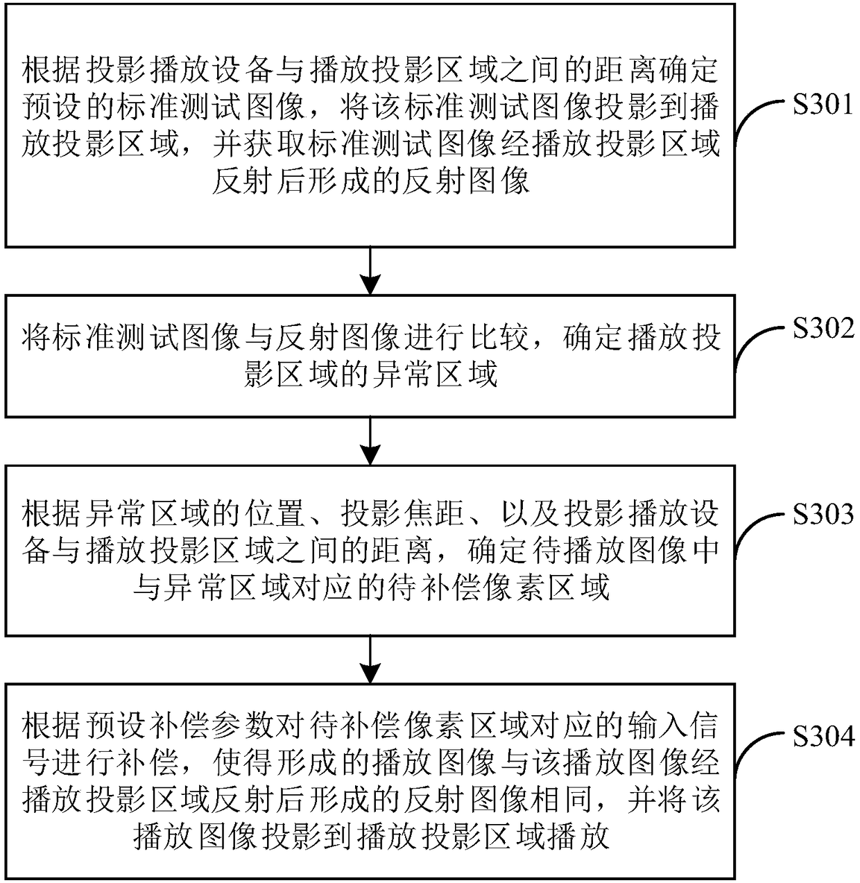
[0056] like image 3 As shown, a specific embodiment of the present invention provides a playback method of a projection playback device, and the playback method includes:
[0057] S301, determine a preset standard test image according to the distance between the projection playback device and the playback projection area, project the standard test image to the playback projection area, and obtain the reflection image formed by the standard test image after being reflected in the playback projection area;
[0058] S302, comparing the standard test image with the reflection image to determine the abnormal area in the playback projection area;
[0059] S303, according to the position of the abnormal area, the projection focal length, and the distance between the projection playback device and the playback projection area, determine the pixel area to be compensated corresponding to the abnormal area in the image to be played;
[0060] S304. Compensate the input signal corresponding to the pixel area to be compensated according to the preset compensation parameter, so that the formed playback image is the same as the reflected image formed by the playback image reflected by the playback projection area, and project the playback image to the playback projection area for playback .
[0061] The playback method of the projection playback device provided by the specific embodiment of the present invention, because the playback method first determines the abnormal area of the playback projection area before playing the image, then determines the pixel area to be compensated corresponding to the abnormal area in the to-be-played image, and finally according to The preset compensation parameter compensates the input signal corresponding to the pixel area to be compensated, so that the formed playback image is the same as the reflection image formed after the playback image is reflected by the playback projection area, and the playback image is projected to the playback projection area for playback; therefore, Compared with the prior art, since the specific embodiment of the present invention compensates the input signal corresponding to the pixel area to be compensated corresponding to the abnormal area, the formed playback image is the same as the reflected image formed by the playback image reflected by the playback projection area, Therefore, the specific embodiment of the present invention can reduce the distortion of the viewing image caused by the uneven surface of the playback projection area when the playback image formed after compensation is played in the playback projection area with uneven surface.
[0062] For the above-mentioned step S302, compare the standard test image with the reflection image, and determine the abnormal area of the playback projection area:
[0063] Specifically, the specific embodiment of the present invention compares the standard test image with the reflected image, and determines the abnormal area in the playback projection area, including: dividing the standard test image into several areas, and comparing the brightness value of each area with the corresponding area of the reflected image. The brightness values are compared, and when the absolute value of the difference between the two brightness values exceeds the set brightness threshold range, the area corresponding to the set brightness threshold range is determined as the abnormal area of the playback projection area.
[0064] During specific implementation, the specific embodiment of the present invention divides the standard test image into several areas, and the size of each area can be equal to the size of one pixel, of course, it can also be equal to the set size of multiple pixels. The standard test image The size of the divided areas is divided according to the actual situation and the needs of the user; in addition, the brightness threshold range set in the specific embodiment of the present invention can also be set according to the actual situation and according to the needs of the user.
[0065] During specific implementation, the specific embodiment of the present invention can use software for detecting bright spots to compare the brightness value of each area divided by the standard test image with the brightness value of the corresponding area of the reflected image. When the absolute value of the difference between the two brightness values When it exceeds the set brightness threshold range, the area corresponding to the set brightness threshold range is determined as the abnormal area of the playback projection area.
[0066] For the above-mentioned step S303, according to the position of the abnormal area, the projection focal length, and the distance between the projection playback device and the playback projection area, determine the pixel area to be compensated corresponding to the abnormal area in the to-be-played image:
[0067] Specifically, as Figure 4 As shown, each pixel included in the projection playback device 01 has a corresponding area in the playback projection area 03, and the corresponding relationship is determined by the focal length of the projection playback device 01 and the distance between the projection playback device 01 and the playback projection area 03. The device 01 can determine the corresponding relationship between the pixels included in the projection and playback device 01 and the playback projection area 03 according to the calculation module provided therein. The specific determination method is similar to that in the prior art, and will not be repeated here.
[0068] For the preset compensation parameters in the above step S304, such as Figure 5 As shown, the method for determining the preset compensation parameter in the specific embodiment of the present invention includes:
[0069] S501, according to the position of the abnormal area, the projection focal length, and the distance between the projection playback device and the playback projection area, determine the abnormal pixel area corresponding to the abnormal area in the standard test image;
[0070] S502, input a plurality of brightness adjustment parameters with different brightness to the pixels included in the abnormal pixel area, form a plurality of test images, and project each formed test image to the playback projection area;
[0071] S503, obtaining the third image formed after each test image is reflected by the playback projection area;
[0072] S504: Compare the brightness value of the standard test image at the position corresponding to the abnormal area with the brightness value of each third image at the position corresponding to the abnormal area, and compare the absolute value of the difference between the two within the set brightness threshold range A plurality of brightness adjustment parameters are averaged to obtain an average brightness adjustment parameter, and the average brightness adjustment parameter is used as a preset compensation parameter.
[0073] Specifically, in the above-mentioned step S501 of the specific embodiment of the present invention, the abnormal pixel area corresponding to the abnormal area in the standard test image is determined, which is similar to the above-mentioned step S303 of the specific embodiment of the present invention, and will not be repeated here.
[0074] Preferably, the standard test image in the specific embodiment of the present invention is a solid color image.
[0075] For the above-mentioned step S502, inputting a plurality of brightness adjustment parameters with different brightness to the pixels included in the abnormal pixel area, during the specific implementation, for the standard test image, if the input brightness value of the pixels included in the abnormal pixel area is R1, the present invention is specifically In the embodiment, according to the preset brightness adjustment parameters, the brightness values R1+L, R1+2L, R1+3L, R1-L, R1-2L, R1-3L, etc. are respectively input to the pixels included in the abnormal pixel area; here L In order to set according to the actual production situation and user needs.
[0076] Compensation for the input signal corresponding to the pixel area to be compensated according to the preset compensation parameter for the above step S304, including:
[0077] If the difference between the luminance value of the standard test image at the position corresponding to the abnormal area and the luminance value of each third image at the position corresponding to the abnormal area is greater than zero, the luminance signal corresponding to the pixel area to be compensated corresponds to the average luminance adjustment parameter After summing the brightness signals, the output is output to the pixel area to be compensated;
[0078] If the difference between the luminance value of the standard test image at the position corresponding to the abnormal area and the luminance value of each third image at the position corresponding to the abnormal area is less than zero, the luminance signal corresponding to the pixel area to be compensated corresponds to the average luminance adjustment parameter The difference of the brightness signal is output to the pixel area to be compensated.
[0079] In addition, in the above-mentioned step S302 of the specific embodiment of the present invention, comparing the standard test image with the reflection image specifically includes: dividing the standard test image into several regions, and comparing the brightness value of each region with the brightness value of the corresponding region of the reflection image. , when the absolute value of the difference between the two brightness values satisfies the set brightness threshold range, it is considered that there is no abnormal area in the playback projection area, and the image to be played can be directly played in the playback projection area subsequently.
[0080] Based on the same inventive concept, a specific embodiment of the present invention also provides a computer storage medium, where the computer storage medium stores a program corresponding to the playback method of the above-mentioned projection and playback device.
[0081]As will be appreciated by those skilled in the art, the present invention includes apparatuses for performing one or more of the operations described in this application. These devices may be specially designed and manufactured for the required purposes, or they may include those known in general purpose computers. These devices have computer programs stored in them that are selectively activated or reconfigured. Such a computer program may be stored in a device (eg, computer) readable medium including, but not limited to, any type of medium suitable for storing electronic instructions and coupled to a bus, respectively Types of disks (including floppy disks, hard disks, CD-ROMs, CD-ROMs, and magneto-optical disks), ROM (Read-Only Memory, read-only memory), RAM (Random Access Memory, random access memory), EPROM (Erasable Programmable Read-Only Memory, Erasable Programmable Read-Only Memory), EEPROM (Electrically Erasable Programmable Read-Only Memory, Electrically Erasable Programmable Read-Only Memory), flash memory, magnetic card or optical card. That is, a readable medium includes any medium that stores or transmits information in a form that can be read by a device (eg, a computer).
[0082] Based on the same inventive concept, a specific embodiment of the present invention also provides a projection and playback device, such as Image 6 As shown, the projection and playback device includes: a comparison module 61, a pixel determination module 62, a compensation module 63 and a projection module 64;
[0083] The projection module 64 is used for determining a preset standard test image according to the distance between the projection and playback device and the playback projection area, and projecting the standard test image to the playback projection area; and for the playback image formed after compensation by the compensation module Projects to the playback projection area.
[0084] The comparison module 61 is used to obtain a reflection image formed by the standard test image reflected in the playback projection area; and compare the standard test image with the reflection image to determine the abnormal area of the playback projection area.
[0085] The pixel determination module 62 is used to determine the pixel area to be compensated corresponding to the abnormal area in the image to be played according to the position of the abnormal area, the projection focal length, and the distance between the projection playback device and the playback projection area.
[0086] The compensation module 63 is used for compensating the input signal corresponding to the pixel area to be compensated according to the preset compensation parameters, so that the formed playback image is the same as the reflected image formed by the playback image reflected by the playback projection area.
[0087] Preferably, the comparison module 61 in the specific embodiment of the present invention is specifically used to divide the standard test image into several areas, and compare the brightness value of each area with the brightness value of the corresponding area of the reflected image. When the absolute value of the difference exceeds the set brightness threshold range, the area corresponding to the set brightness threshold range is determined as the abnormal area of the playback projection area.
[0088] Preferably, the pixel determination module 62 in the specific embodiment of the present invention is also used to determine the corresponding abnormal area in the standard test image according to the position of the abnormal area, the projection focal length, and the distance between the projection playback device and the playback projection area. Abnormal pixel area.
[0089] The projection module 64 is further configured to project each formed test image to the playback projection area; the test image is an image formed after inputting brightness adjustment parameters with different brightness to the pixels included in the abnormal pixel area.
[0090] The comparison module 61 is also used to obtain the third image formed after each test image is reflected by the playback projection area; The brightness values of the three images are compared, and an average brightness adjustment parameter is obtained by averaging a plurality of brightness adjustment parameters whose absolute value of the difference between the two is within the range of the set brightness threshold to obtain an average brightness adjustment parameter, and the average brightness adjustment parameter is used as a preset compensation parameter .
[0091] Preferably, the compensation module 63 in the specific embodiment of the present invention is specifically configured to, if the difference between the brightness value of the standard test image at the position corresponding to the abnormal area and the brightness value of each third image at the corresponding position of the abnormal area is greater than zero. , the luminance signal corresponding to the pixel area to be compensated and the luminance signal corresponding to the average luminance adjustment parameter are summed and output to the pixel area to be compensated.
[0092] In the specific embodiment of the present invention, the compensation module 63 is specifically configured to, if the difference between the luminance value of the standard test image at the position corresponding to the abnormal area and the luminance value of each third image at the position corresponding to the abnormal area is less than zero, the difference between The difference between the luminance signal corresponding to the compensation pixel area and the luminance signal corresponding to the average luminance adjustment parameter is calculated and output to the pixel area to be compensated.
[0093] To sum up, a specific embodiment of the present invention provides a playback method for a projection playback device, comprising: determining a preset standard test image according to the distance between the projection playback device and the playback projection area, and projecting the standard test image onto a Play the projection area, and obtain the reflection image formed by the standard test image reflected by the projection area; compare the standard test image with the reflection image to determine the abnormal area of the projection area; The distance between the device and the playback projection area determines the pixel area to be compensated corresponding to the abnormal area in the to-be-played image; the input signal corresponding to the to-be-compensated pixel area is compensated according to preset compensation parameters, so that the formed playback image is the same as the playback image. The reflected image formed after being reflected in the playback projection area is the same, and the playback image is projected to the playback projection area for playback. Compared with the prior art, since the embodiment of the present invention compensates the input signal corresponding to the pixel area to be compensated corresponding to the abnormal area, the formed playback image is the same as the reflected image formed after the playback image is reflected by the playback projection area. , when the playback image formed after compensation is played in the playback projection area with uneven surface, the distortion of the viewing image caused by the uneven surface of the playback projection area can be reduced.
[0094] The above are only some embodiments of the present invention. It should be pointed out that for those skilled in the art, without departing from the principles of the present invention, several improvements and modifications can be made. It should be regarded as the protection scope of the present invention.
PUM


Description & Claims & Application Information
We can also present the details of the Description, Claims and Application information to help users get a comprehensive understanding of the technical details of the patent, such as background art, summary of invention, brief description of drawings, description of embodiments, and other original content. On the other hand, users can also determine the specific scope of protection of the technology through the list of claims; as well as understand the changes in the life cycle of the technology with the presentation of the patent timeline. Login to view more.