Cup base component mounting structure of glass stirring cup

A mixing cup holder and component installation technology, which can be applied to home appliances, applications, kitchen utensils, etc., can solve problems such as poor precision, unfavorable disassembly and maintenance, and misalignment, and achieve the effect of reducing assembly costs and good assembly effects

Pending Publication Date: 2018-05-29
FOSHAN VIOMI ELECTRICAL TECH +1
View PDF8 Cites 10 Cited by
  • Summary
  • Abstract
  • Description
  • Claims
  • Application Information

AI Technical Summary

Problems solved by technology

There is generally a heating plate at the bottom of the chassis, and a handle is provided outside the glass. The handle needs to be connected to the cup holder in addition to the connection with the glass cup. Therefore, the cup holder needs to ensure the connection with the glass cup so that the bottom opening of the glass cup is sealed. , and it is necessary to ensure that the position of the connection with the handle is aligned. Therefore, the difficulty of installation is greatly increased, and it is easy to appear dislocation, looseness, water leakage and other phenomena during assembly.
In addition, due to the poor rigor of assembly in this way, it is easy to generate noise
In addition, since the surface of the cup holder is basically a smooth structure, it is not conducive to disassembly and maintenance.

Method used


Image

  • Cup base component mounting structure of glass stirring cup
  • Cup base component mounting structure of glass stirring cup
  • Cup base component mounting structure of glass stirring cup

Examples


Embodiment Construction

[0029] The present invention will be further described below in conjunction with accompanying drawing and embodiment:

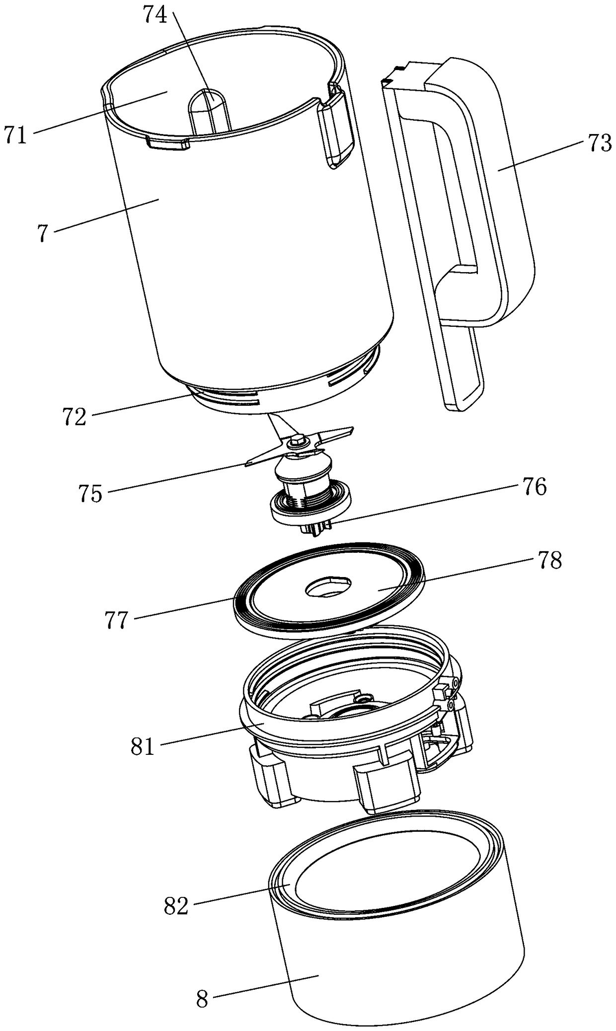
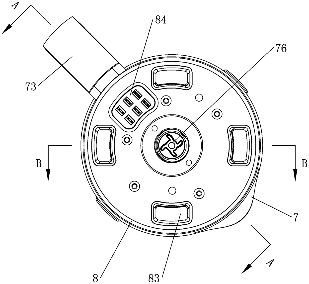
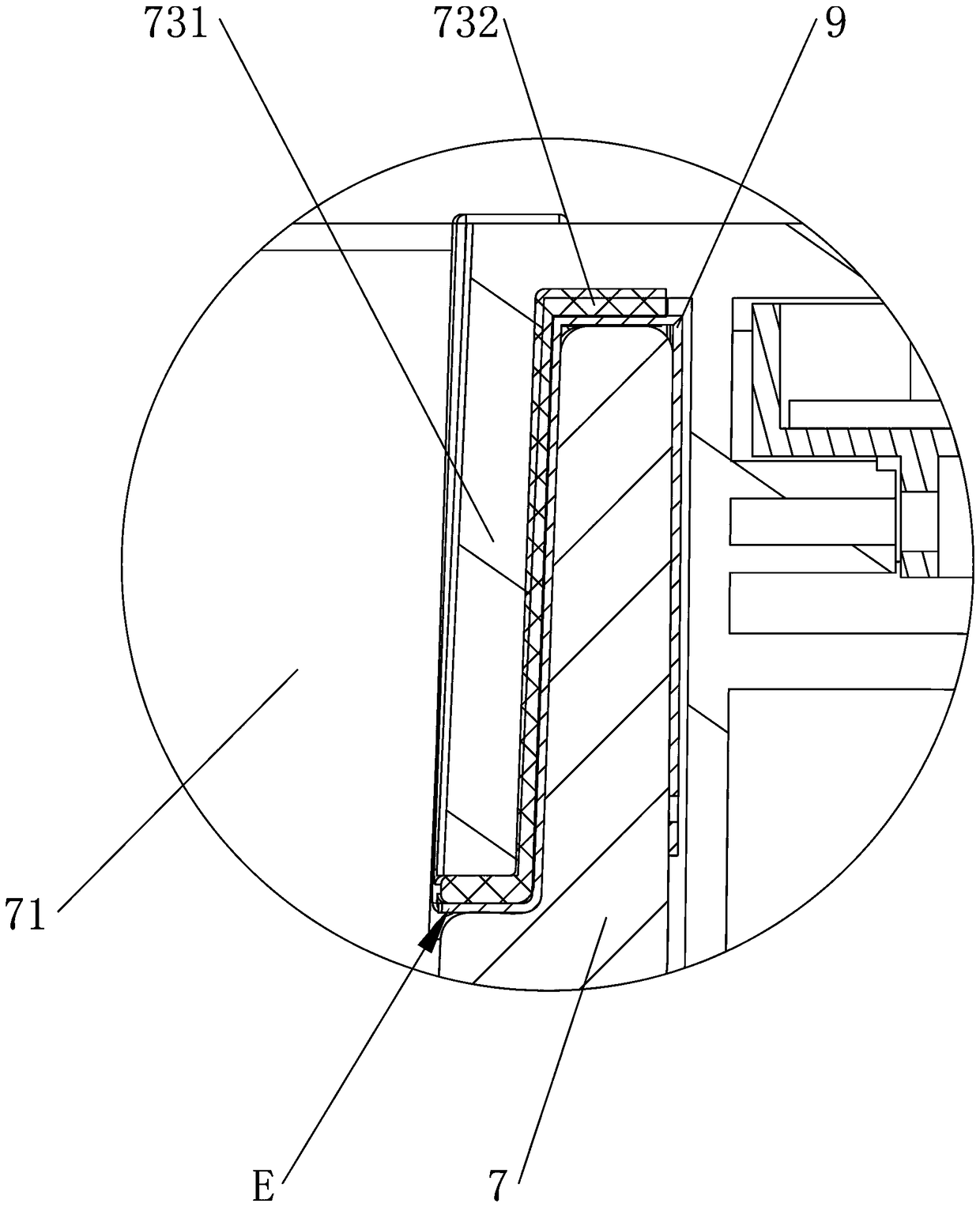
[0030] see Figure 1 to Figure 9 As shown, a glass stirring cup holder assembly installation structure includes a cup body 7, a knife set 75, a chassis 78 and a cup holder 8. The knife set 75 is rotatably arranged on the chassis 78 and is located in the inner cavity 71 of the cup body 7. The bottom opening 72 of the cup body 7, the chassis 78 covers the opening 72, and also includes a cup inner frame 81, which is arranged in the cup holder 8, and the top of the cup inner frame 81 is provided with a cavity, and the inner wall of the cavity is provided with a platform , chassis 78 is arranged on the bearing platform, and chassis 78 edge is provided with inner sealing ring 77, and the inner wall of concave cavity corresponding bearing platform top is threadedly connected with cup body 7 bottoms, and inner sealing ring 77 and chassis 78 edges are pressed on openi...


PUM


Abstract

The invention relates to a cup base component mounting structure of a glass stirring cup. The cup base component mounting structure comprises a cup body, a cutter set, a base plate, a cup base and aninner cup frame. The cutter set is rotationally arranged on the base plate, and is located in an inner cavity of the cup body. An opening is formed in the bottom of the cup body. The base plate coversthe opening. The inner cup frame is arranged in the cup base. A cavity is formed in the top of the inner cup frame. A carrying platform is arranged on the inner wall of the cavity. The base plate isarranged on the carrying platform. An inner seal ring is arranged at the edge of the base plate. The inner wall, corresponding to the upper side of the carrying platform, of the cavity is in threadedconnection with the lower portion of the cup body. The inner seal ring and the edge of the base plate are compressed at the bottom of the opening. The cup base component mounting structure has the advantages that the inner cup frame is added to the cup base component mounting structure and is assembled with the base plate, and the bottom of the inner cup frame is connected to the outer portion ofthe cup base directly, so that the assembly effect is good, and water leakage caused by malalignment due to inaccurate assembly of the cup base and a glass cup is avoided.

Description

technical field [0001] The invention relates to a stirring cup for a food cooking machine body, in particular to an installation structure of a glass stirring cup cup seat assembly. Background technique [0002] The structure of the existing glass stirring cup is roughly as follows: it includes a glass, a cup holder, a knife set and a chassis, the bottom of the glass is open, the cup holder fixes the chassis outside the opening, and the knife set is rotatably arranged on the chassis. A sealing ring is arranged on the outer periphery of the chassis, and the sealing ring seals the opening at the bottom of the glass cup. There is generally a heating plate at the bottom of the chassis, and a handle is provided outside the glass. The handle needs to be connected to the cup holder in addition to the connection with the glass cup. Therefore, the cup holder needs to ensure the connection with the glass cup so that the bottom opening of the glass cup is sealed. , and it is necessary...

Claims


Application Information

Patent Timeline
Patent Type & Authority Applications(China)
IPC IPC(8): A47J43/07A47J43/046
CPCA47J43/046A47J43/07A47J43/0722
Inventor 陈小平
Owner FOSHAN VIOMI ELECTRICAL TECH
Why Eureka
Try Eureka