Manipulation input device and electronic instrument using the same

Inactive Publication Date: 2008-07-17
ORMON CORPORATION
View PDF1 Cites 12 Cited by
  • Summary
  • Abstract
  • Description
  • Claims
  • Application Information

AI Technical Summary

Benefits of technology

[0009]In the first aspect of the present invention, the mounting portion extended downward from the outer circumferential edge portion of the ring-shape plate spring is fixed to the outer circumferential edge portion of the upper surface of the base. Therefore, unlike the conventional technique, it is not necessary that the elastic engagement holder be cut and raised in the base, and it is not necessary to avoid the elastic engagement holder when the manipulation input device is assembled in the chassis of the cellular phone. As a result, an installation space can be reduced in the chassis to obtain the low-profile manipulation input device having the excellent assembly property.
[0010]In the manipulation input device according to the first aspect of the present invention, preferably a resin pedestal portion is integrally molded in a metal ring-shape plate spring. Accordingly, because the metal material having excellent strength is used as the ring-shape plate spring, the ring-shape plate spring is hardly broken to improve durability, and the ring-shape plate spring can be thinned compared with the conventional technique. The whole of the manipulation member is thinned, so that the ring magnet of the manipulation dial rotatably supported by the upper surface of the manipulation member can be disposed near the magnetic-field detection element mounted in the upper surface of the printed-circuit board. Therefore, sensitivity of the magnetic-field detection element is improved and the low-profile ring magnet is used, so that the whole of the manipulation input device can further be thinned.
[0013]Accordingly, because the push button disposed in the center of the manipulation dial is always biased by the ring spring, looseness is eliminated to obtain the manipulation input device having a comfortable manipulation feeling,
[0015]In accordance with the present invention, the low-profile electronic instrument in which the magnetic property of the magnetic-field detection element can effectively be used is obtained.

Problems solved by technology

Because the manipulation plate 150 of the manipulation input device is formed by a resin molded component, fatigue fracture is easily generated by a repeatedly-applied pressing-down force.
Therefore, even if the thickness of the manipulation plate is decreased to thin the manipulation input device, there is a limitation to the thinning.
Additionally, the limitation to the thinning of the manipulation plate increases a distance between the ring magnet of the manipulation dial rotatably supported by the upper surface of the manipulation plate and the magnetic-field detection element mounted in the upper surface of the printed-circuit board.
Accordingly, a height of the whole of the manipulation input device is increased, which results in a problem in that the manipulation input device cannot be thinned.

Method used


Image

  • Manipulation input device and electronic instrument using the same
  • Manipulation input device and electronic instrument using the same
  • Manipulation input device and electronic instrument using the same

Examples


Embodiment Construction

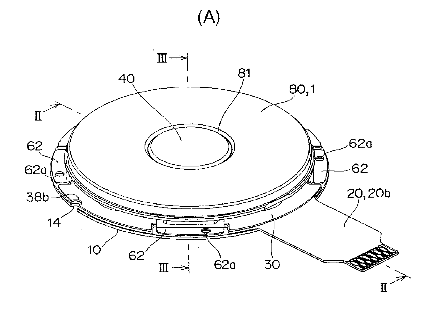
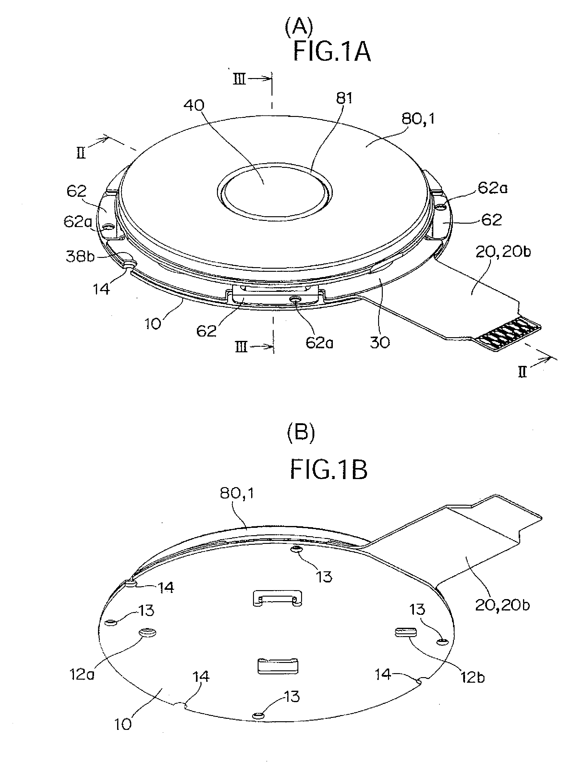
[0028]A manipulation input device according to a preferred embodiment of the present invention will be described below with reference to the accompanying drawings of FIGS. 1 to 11. A manipulation input device 1 according to an embodiment has a thickness of about 2 mm, and the manipulation input device 1 is used when a scroll bar in a monitor of a cellular phone is scrolled to perform selection and instruction.

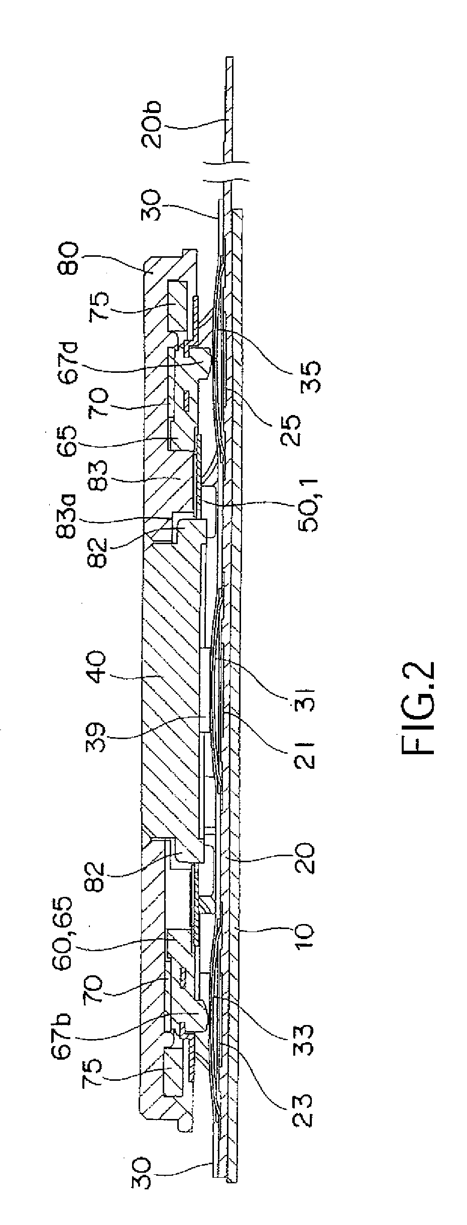
[0029]As shown in FIGS. 4 to 8, the manipulation input device 1 includes a metal base 10, a printed-circuit board 20, a push button 40, a fixing ring 50, a manipulation member 60, a slide sheet 70, a ring magnet 75, and a manipulation dial 80. The printed-circuit board 20 is formed of a flexible resin film, and the printed-circuit board 20 is coated with an insulating sheet 30.

[0030]As shown in FIG. 5, the metal base 10 has a substantially circular shape when viewed from above, and a pair of positioning projections 11a and 11b are cut and raised upward in a central portion of t...


PUM


Abstract

A manipulation input device includes a base, a printed-circuit board adhered to the base, a manipulation member, a pressing projection, and a manipulation dial. A plurality of push-button switches and a magnetic-field detection element are mounted on the printed-circuit board. The manipulation member has a ring-shape plate spring and a pedestal portion. The pressing projection press-contacts the push-button switch by fixing a mounting portion to an outer circumferential edge of the upper surface of the base. The pressing projection is provided toward a lower surface of the pedestal portion. The mounting portion is extended downward from an outer circumferential edge portion of the ring-shape plate spring. A ring magnet is assembled in a lower surface of the manipulation dial. N poles and S poles are alternatively arranged in the ring magnet. The manipulation dial is rotatably assembled in an upper surface of the pedestal portion.

Description

BACKGROUND OF THE INVENTION[0001]1. Field of the Invention[0002]The present invention relates to a manipulation input device suitable to a cellular phone and a portable music player, particularly to a low-profile manipulation input device.[0003]2. Description of the Related Art[0004]Conventionally, for example, as shown in FIG. 12, there is a manipulation input device used in the cellular phone including a base 110, a printed-circuit board 120, a manipulation plate 150, and a disc-type manipulation dial 170. A plurality of push-button switches and a magnetic-field detection element are mounted in an upper surface of the printed-circuit board 120, and the printed-circuit board 120 is integral with the base 110 by stacking the printed-circuit board 120 on the base 110. The manipulation plate 150 is placed on the printed-circuit board 120. A ring magnet 165 in which N poles and S poles are alternately arranged is assembled in a lower surface of the manipulation dial 170, and the manipu...

Claims


Application Information

Patent Timeline
IPC IPC(8): H05K7/00
CPCH01H19/005H01H25/041H01H2025/048H01H2025/043H01H2019/006H04M1/23H01H13/02
Inventor MIYASAKA, TAKESHITANAKA, MASAYUKI
Owner ORMON CORPORATION
Why Eureka
Try Eureka