Feeding mounting device of releaser

An installation device and releaser technology, applied in metal processing, metal processing equipment, manufacturing tools, etc., can solve the problems of poor operation convenience, low detection efficiency, inconvenient assembly, etc., and achieve high accuracy, reasonable structure, and reasonable detection process. Effect

Active Publication Date: 2017-05-10
ZHEJIANG ORIENTX FIRE SAFETY EQUIP
View PDF8 Cites 11 Cited by
  • Summary
  • Abstract
  • Description
  • Claims
  • Application Information

AI Technical Summary

Problems solved by technology

The structure of the fire extinguisher releaser (that is, the fire extinguisher valve) should include four parts: the upper valve seat, the ejector rod with the valve core, the spring and the riser seat. At present, the installation of the fire extinguisher valve is mainly done manually or mechanically semi-automatically. , during assembly, the form of sequential assembly is adopted, which is inefficient and inconvenient to assemble; in addition, after the assembly is completed and before leaving the factory, it is installed on the actual fire extinguisher tank for detection, which has low detection efficiency and poor operation convenience

Method used


Image

  • Feeding mounting device of releaser
  • Feeding mounting device of releaser
  • Feeding mounting device of releaser

Examples


Embodiment 1

[0033] Embodiment 1: as Figure 1 to Figure 5In the shown embodiment, a feed installation device for a releaser is suitable for the assembly of a fire extinguisher valve (also called a releaser). The releaser 1 includes an upper valve seat 11, a push rod 12, a spring 13 and a stand Pipe seat 14, the upper valve seat is provided with valve inner passage 11a, and the upper sealing ring and the spool 12b for blocking the valve inner passage are arranged on the push rod, the upper sealing ring is at the top of the valve core, and the upper end of the upper valve seat is provided with There is an upper through hole connected with the passage in the valve, the upper sealing ring can slide and seal with the upper through hole, the upper sealing ring can be squeezed with the upper through hole, and the side wall of the upper valve seat is provided with an outlet connected with the passage in the valve Road 11b, the lower end of the upper valve seat is provided with an inlet passage co...

Embodiment 2

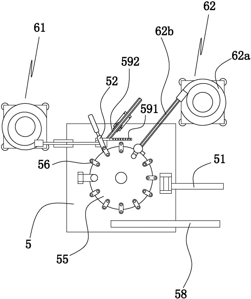
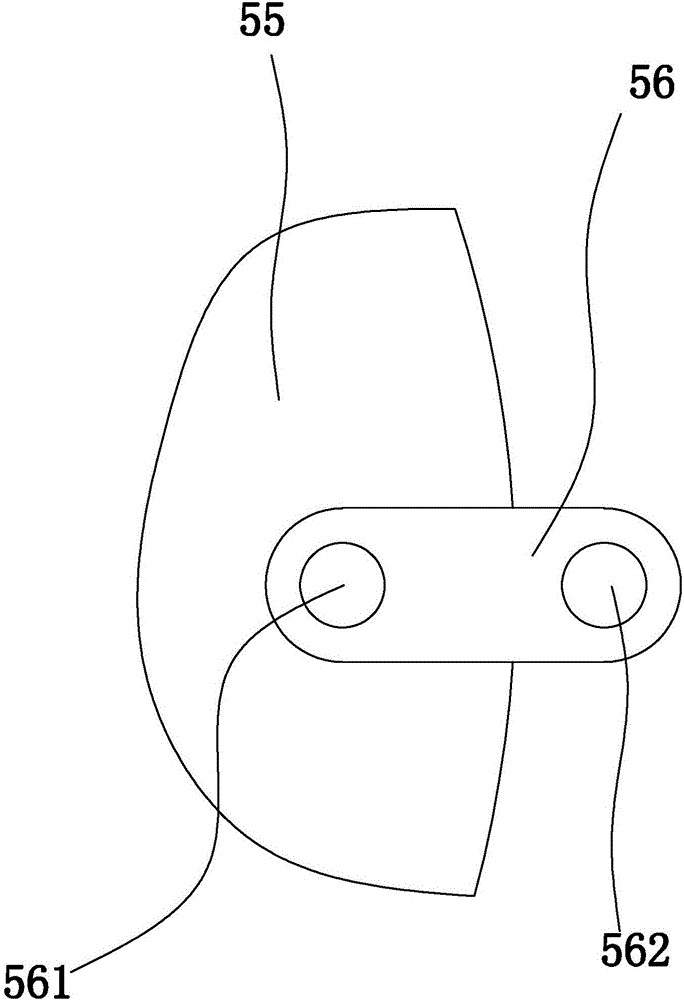
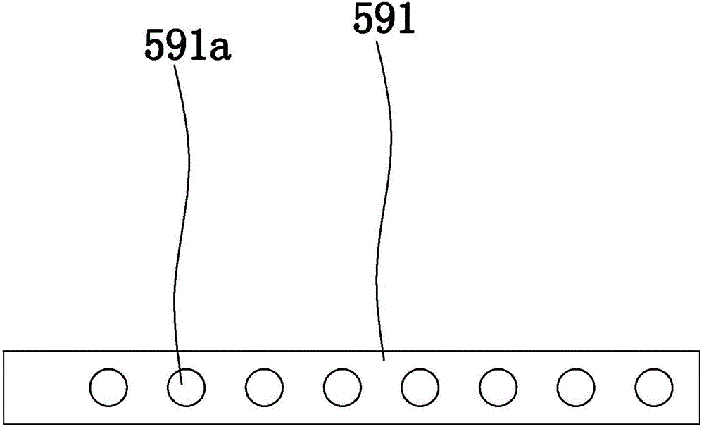
[0053] Embodiment 2: the basic structure and implementation mode of this embodiment are the same as embodiment 1, and its difference is, as Figure 6 to Figure 8 As shown in , the main workbench is equipped with a medium circulation detection device, which includes a first valve seat clamping manipulator for fixing the upper valve seat, a valve seat below the first valve seat clamping manipulator The first sealing inflatable seat 21, the blown structure 22 for being blown by the outlet jet airflow, and the valve opening structure 23 for pressing down the ejector rod, the valve opening structure includes a pressing plate 23a for pressing down the ejector rod and for driving The valve-opening electric cylinder 23b that the pressure plate moves up and down, the blown structure includes the blown seat 22a, the spring seat 22b arranged on the blown seat, the marking groove arranged on the blown seat, the blown spring 22c connected with the spring seat and The blown block 22d connec...


PUM


Abstract

The invention discloses a feeding mounting device of a releaser. The feeding mounting device comprises a vertical tube seat vibration plate, an ejection rod vibration plate, a main workbench, a rotary table, a vertical tube seat rotating structure, an upper valve seat transfer assembly robot, an upper valve seat assembly fixing robot and a finished product taking robot, wherein an upper valve seat loading robot, a vertical tube seat loading robot, an ejection rod loading assembly robot and an upper valve seat initial assembly fixing robot are arranged on the main workbench; a plurality of temporary fixtures are arranged on the rotary table, and a vertical tube seat accommodating groove and an upper valve seat accommodating groove are formed in each temporary fixture; a first vertical through hole communicating with each vertical tube seat accommodating groove is formed in the lower end of the vertical tube seat accommodating groove, and a second vertical through hole communicating with each valve body accommodating groove is formed in the lower end of each upper valve seat accommodating groove; and the vertical tube seat rotating structure comprises a rotary clamp head, an assembly motor and an assembly cylinder. The feeding mounting device has the beneficial effects that the structure is reasonable, the releaser can be assembled effectively, the automation degree is high, the assembly efficiency is high, and the effect is good.

Description

technical field [0001] The invention belongs to the technical field of fire extinguishers, in particular to a feed installation device for a releaser. Background technique [0002] A fire extinguisher is a portable fire extinguishing tool. Chemicals or fire extinguishing gas and solid are placed in the fire extinguisher to put out the fire. Fire extinguishers are one of the common fire prevention facilities. They are stored in public places or places where fires may occur. Different types of fire extinguishers are filled with different ingredients. They are specially designed for different types of fires. Fire extinguishers have various types, functions and use environments. different. At present, the mainstream fire extinguishers basically open the fire extinguisher by pressing the valve, so that the fire extinguishing substance (such as dry powder, special clean gas for fire extinguishing, etc.) in the fire extinguisher is ejected to realize its fire extinguishing functi...

Claims


Application Information

Patent Timeline
Patent Type & Authority Applications(China)
IPC IPC(8): B23P19/00
CPCB23P19/00B23P19/001
Inventor 陈巅杨俊华明翔王春峰
Owner ZHEJIANG ORIENTX FIRE SAFETY EQUIP
Why Eureka
Try Eureka