Rolling bearing apparatus

a technology of rolling bearings and rolling bearings, which is applied in the direction of mechanical devices, bearing units, engine components, etc., can solve the problems of generating noise, poor handling properties, and attributable to new attachment problems, and achieves the effects of suppressing or preventing the concentration of stress, simple structure, and high degree of freedom in shap

Inactive Publication Date: 2011-01-11
JTEKT CORP
View PDF10 Cites 13 Cited by
  • Summary
  • Abstract
  • Description
  • Claims
  • Application Information

AI Technical Summary

Benefits of technology

[0015]The invention has been made in view of the above-described problems, and an object of the invention is to provide a rolling bearing apparatus capable of suppressing deterioration in the roundness of the rolling bearing apparatus and thereby to suppress the generation of noise in a bearing part.
[0016]Further, another object of the invention is to provide a two-split outer ring and a rolling bearing using the same, which can suppress the misalignment in the axial direction and can be attached to the place of use even when the splitting surfaces at both ends of a split part are greatly curved or inflected.
[0017]Furthermore, another object of the invention is to provide a rolling bearing having good assembling properties, in which the degree of freedom in the circular shape of an outer ring is high.

Problems solved by technology

Moreover, the gap in the radial direction within the rolling bearing 110 increases and thereby to generate noise.
On the other hand, when the split bearing ring is split such that the splitting surfaces are linear, the splitting surfaces are likely to be misaligned with each other at the time of attachment and thus the handling properties are poor.
However, a new attachment problem attributable to such a splitting method is generated.
As described forgoing, the splitting process is not stable and it is difficult to form the same splitting surfaces in a controlled manner.
For example, when only one of the splitting surfaces is defective, it cannot be substituted by another one, thereby increasing the cost.
However, curving the metal plate in a semicircular shape is troublesome.
However, such process steps are troublesome.
Therefore, in such a state, it cannot be used as the outer ring of a rolling bearing.

Method used


Image

  • Rolling bearing apparatus
  • Rolling bearing apparatus
  • Rolling bearing apparatus

Examples


first embodiment

[0064]A rolling beating apparatus according to a first embodiment of the invention will be described with reference to FIGS. 1A to 4B.

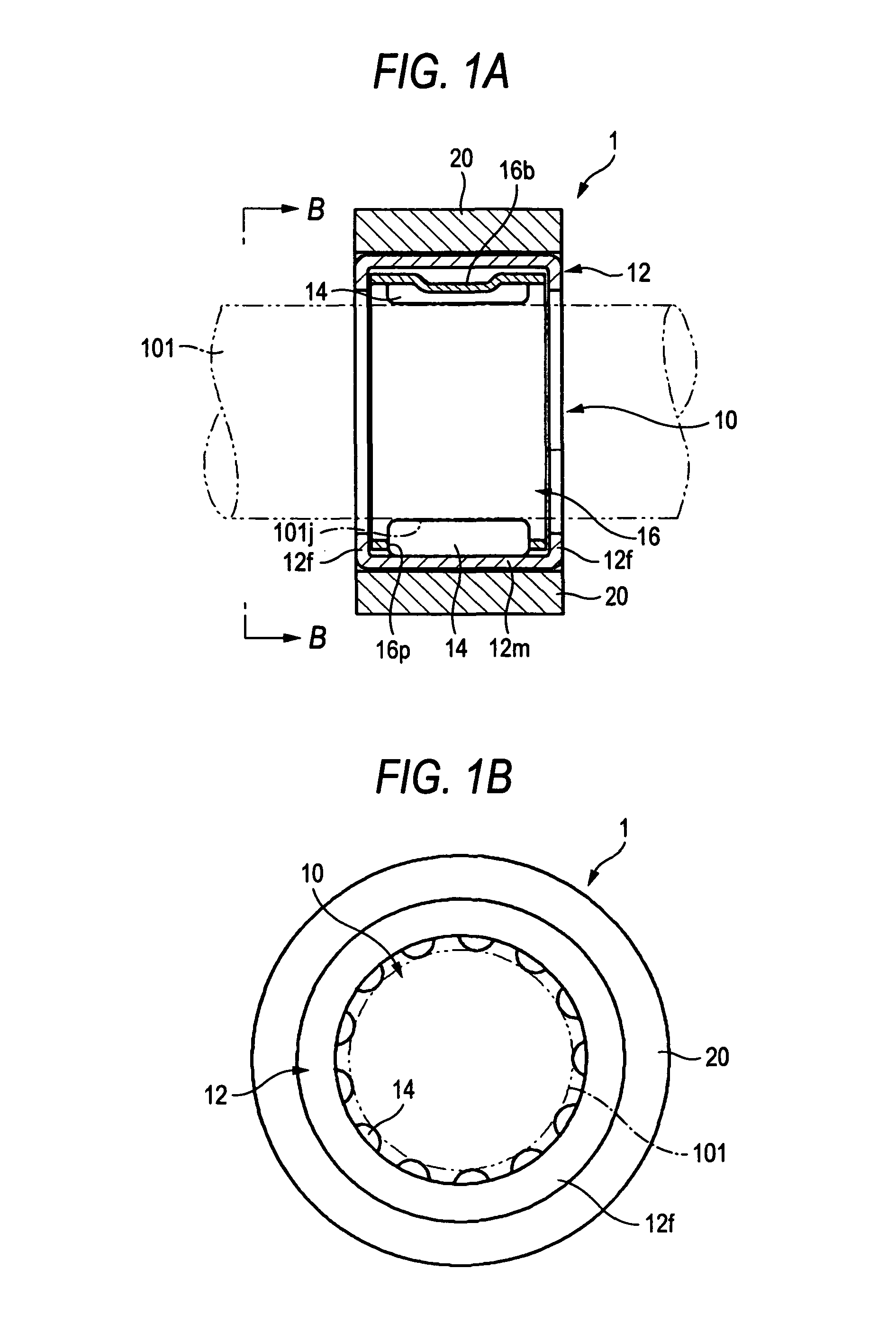
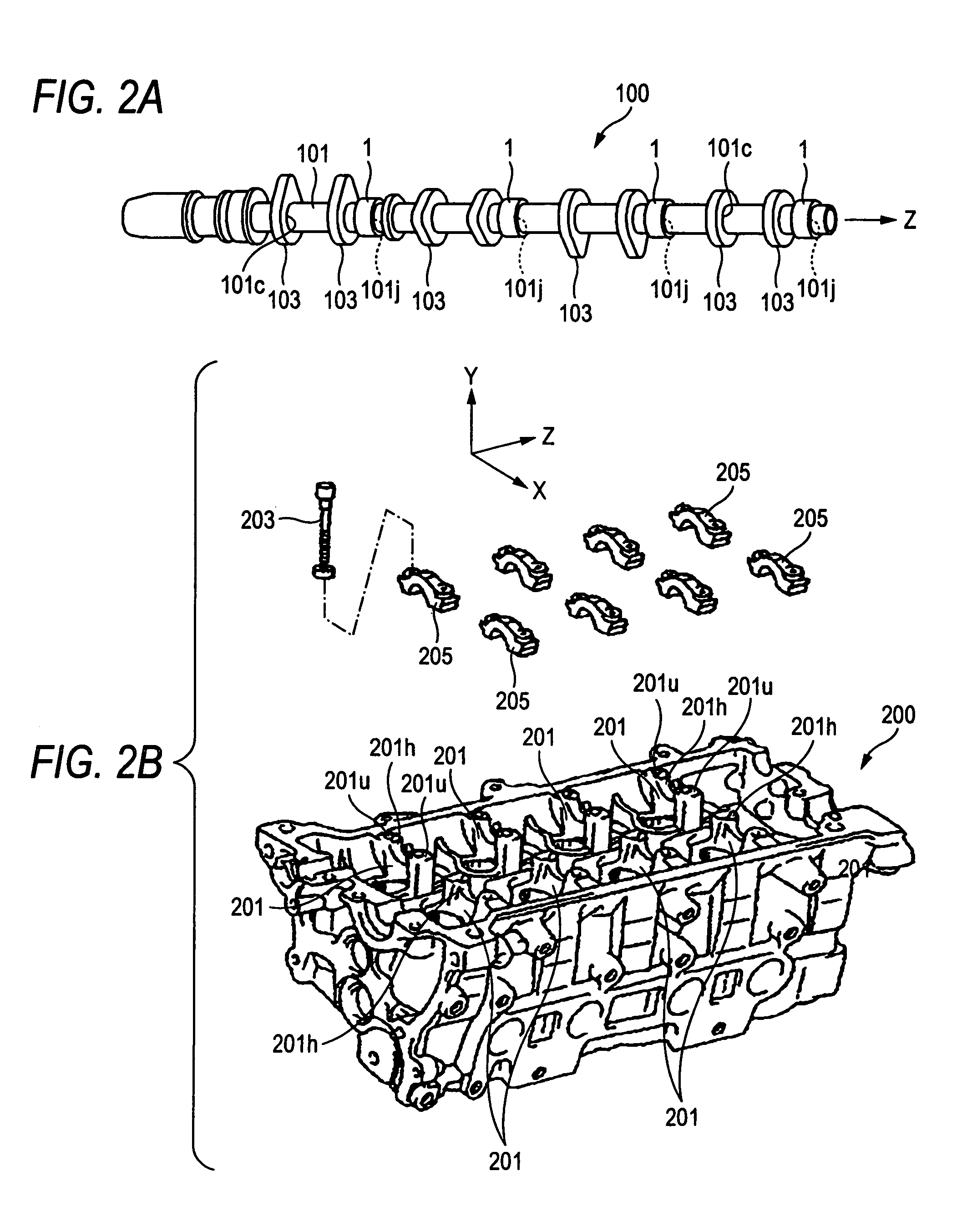
[0065]The rolling bearing apparatus of the present embodiment is a bearing apparatus that rotatably supports a cam shaft attached to a cylinder head of an engine. FIGS. 1A and 1B are longitudinal sectional views of the rolling bearing apparatus. FIGS. 2A and 2B are perspective views of a cam shaft and a cylinder head of an engine, respectively. FIG. 3 is a front view showing the state in which the rolling bearing apparatus is attached to the cylinder head of the engine. FIGS. 4A and 4B are front and top views of a rolling bearing apparatus according to a modification.

[0066]In the drawings, the X direction is a width direction of the cylinder head, the Y direction is a height direction thereof, and the Z direction is a front-rear direction thereof (or the axial direction of the cam shaft).

[0067]200 of Engine and Cam Shaft 100>

[0068]Before describing th...

second embodiment

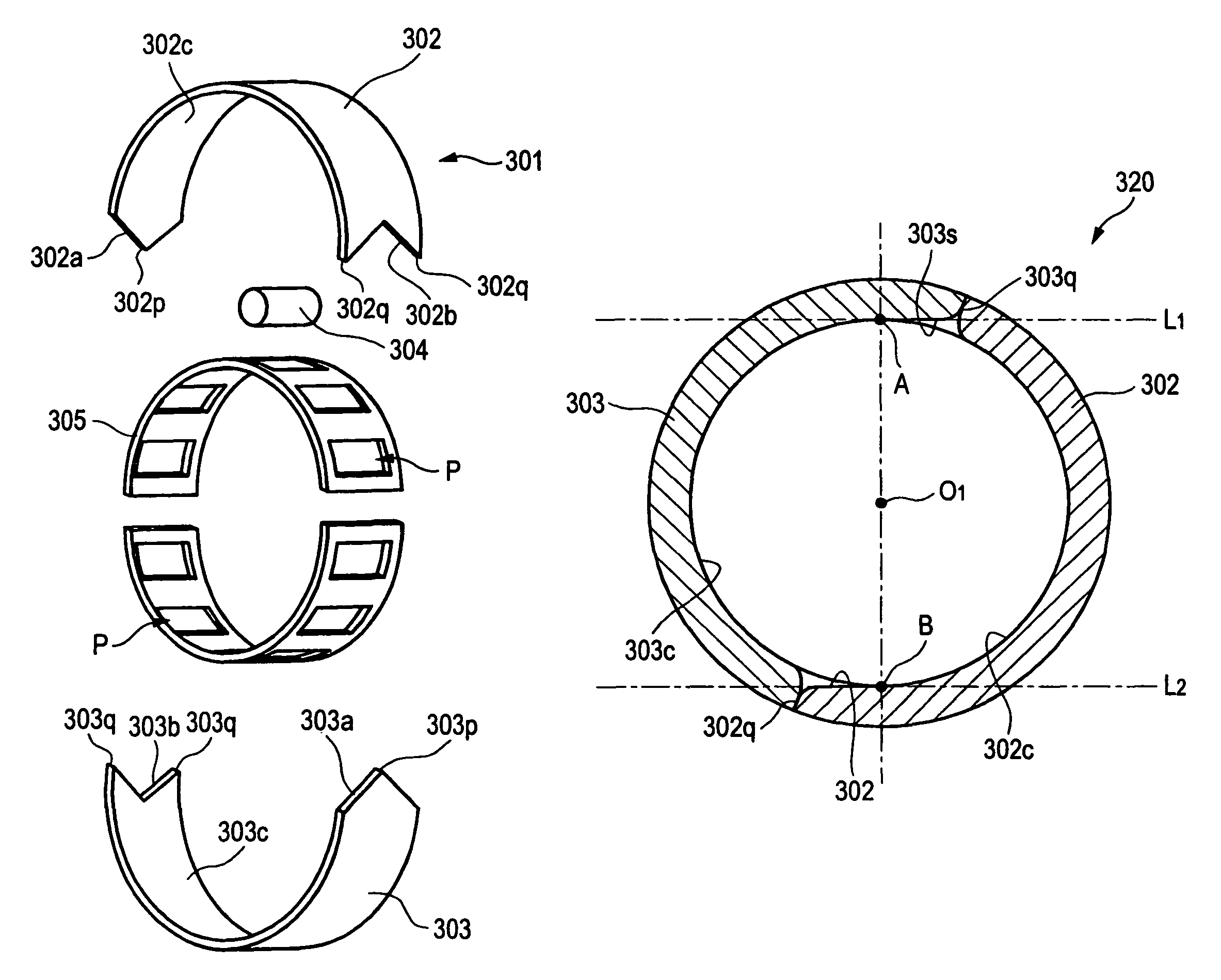
[0089]Hereinafter, a rolling bearing according to a second embodiment of the invention will be described with reference to the drawings. FIGS. 5A and 5B are a side view and a partly omitted, exploded perspective view, respectively, showing an example of a rolling bearing according to the second embodiment of the invention. FIG. 6 is an exploded perspective view showing the state in which the rolling bearing is attached between a crankshaft and a large end part of a connecting rod. FIG. 7 is a sectional view showing the attachment state of the rolling bearing of FIG. 6. FIGS. 8A and 8B are side and front views of a split part constituting an outer ring. FIG. 9 is a side sectional view of an outer ring obtained by assembling the split parts.

[0090]As shown in FIGS. 5A and 5B, a rolling bearing 1 has a two-split outer ring 320 (hereinafter, simply referred to as an outer ring) constituted by a pair of split parts 302 and 303 having a substantially semi-cylindrical shape, a plurality of ...

third embodiment

[0107]Hereinafter, a rolling bearing according to a third embodiment of the invention will be described with reference to the drawings. FIGS. 12A and 12B are a side view and a partly omitted, exploded perspective view, respectively, showing an example of a rolling bearing according to the third embodiment of the invention. FIG. 13 is an exploded perspective view showing the state in which the rolling bearing is attached between a crankshaft and a large end part of a connecting rod. FIG. 14 is a sectional view showing the attachment state of the rolling bearing of FIG. 13FIGS. 15A to 15C are sectional views taken along the lines X-X and Y-Y, respectively. FIG. 16 is an enlarged view of the Z portion in FIGS. 15A to 15C.

[0108]As shown in FIGS. 12A and 12B, a rolling bearing 401 has a two-split outer ring 420 (hereinafter, simply referred to as an outer ring) constituted by a pair of split parts 402 and 403 having a substantially semi-cylindrical shape and elastic members 410 and 410 t...


PUM


Abstract

A rolling bearing apparatus is provided that rotatably supports a cam shaft in a cylinder head of an engine. The rolling bearing apparatus includes a plurality of rolling elements; a cage that positions the rolling elements so as to be spaced at regular intervals from each other in a circumferential direction and that retains the rolling elements in a freely rotatable manner; a shell-type outer ring configured to receive the rolling elements and the cage and having a raceway surface of the rolling elements at an inner side thereof; and an outer ring fastening member formed of a material having almost the same thermal expansion coefficient as the shell-type outer ring and having a press-fit portion press-fitted to the shell-type outer ring.

Description

BACKGROUND OF THE INVENTION[0001]1. Field of the Invention[0002]The present invention relates to a rolling bearing or a rolling bearing apparatus suitably used to rotatably support a cam shaft in a cylinder head of an engine. More specifically, the present invention relates to a two-split outer ring that is split in two parts in the circumferential direction and to a rolling bearing having the same.[0003]2. Related Art[0004]A large end part of a connecting rod, which is a bar for connecting a piston and a crankshaft in an engine, is coupled to the crankshaft with a rolling bearing disposed therebetween. As the rolling bearing, a split bearing ring (outer ring) that is split in two parts, for example, is used because of the features of the crankshaft.[0005]A technology related to the rolling bearing apparatus is described in JP-A-2005-180459, for example.[0006]As shown in FIG. 20, a rolling bearing 110 of Patent Document 1 is a shell bearing that is configured to be attached to a jou...

Claims


Application Information

Patent Timeline
Patent Type & Authority Patents(United States)
IPC IPC(8): F16C33/60
CPCF16C33/516F16C19/466F16C35/077F16C33/60F16C2360/18
Inventor WASEDA, YOSHITAKAOKUMURA, TSUYOSHI
Owner JTEKT CORP
Why Eureka
Try Eureka