
Valve timing controller

a timing controller and valve technology, applied in the direction of bearing unit rigid support, couplings, machines/engines, etc., can solve the problems of affecting the smoothness of the valve, the deterioration of the roundness of the bearing member, and the long time it takes to engage the joint member and the fitting recess, so as to reduce the backlash of the supporting member, improve the anti-wear quality and silence at the time of actuation, and reduce the effect of supporting backlash

Active Publication Date: 2008-04-10
DENSO CORP
View PDF1 Cites 1 Cited by
  • Summary
  • Abstract
  • Description
  • Claims
  • Application Information

AI Technical Summary

Benefits of technology

[0006]It is an object of the present invention to provide a valve timing controller which solves these problems.
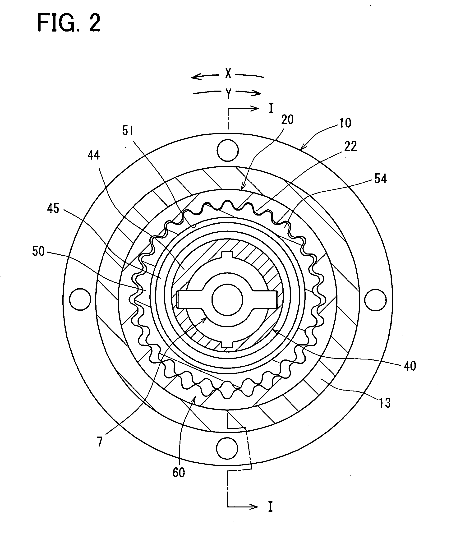
[0008]Thereby, since a rigid variation is reduced in a circumferential direction of an input wall, even if the input wall is press-inserted into the inner circumference of a bearing member to reduce the supporting backlash, a transformation difference is hardly produced in the circumferential direction. As a result, in an input wall, since the configuration distortion of the fitting recess is restrained, the fit assembly at the time of manufacture, the anti-wear quality and silence at the time of actuation can be improved. Moreover, since deterioration of the roundness of the bearing member is restrained even if deformation of the input wall is transferred to the bearing member, the lifetime lowering of the bearing member can be suppressed.

Problems solved by technology

Such a deformation causes a distortion of the fitting recess, so that it will take long time to engage the joint member and the fitting recess.
After assembling, the joint member vibrates in the fitting recess, which causes abrasion and noise.

Method used


Image

  • Valve timing controller
  • Valve timing controller
  • Valve timing controller

Examples


first embodiment

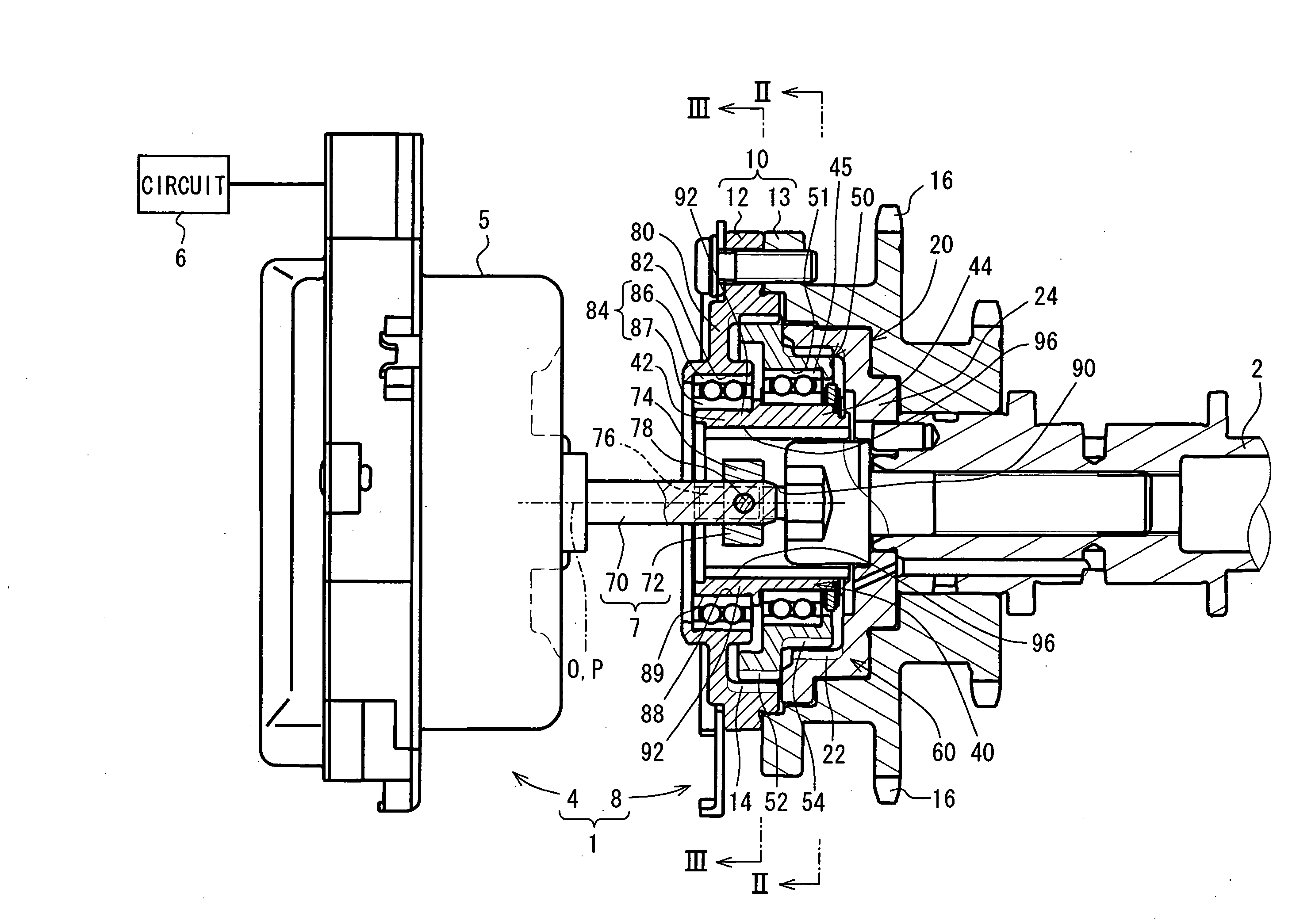
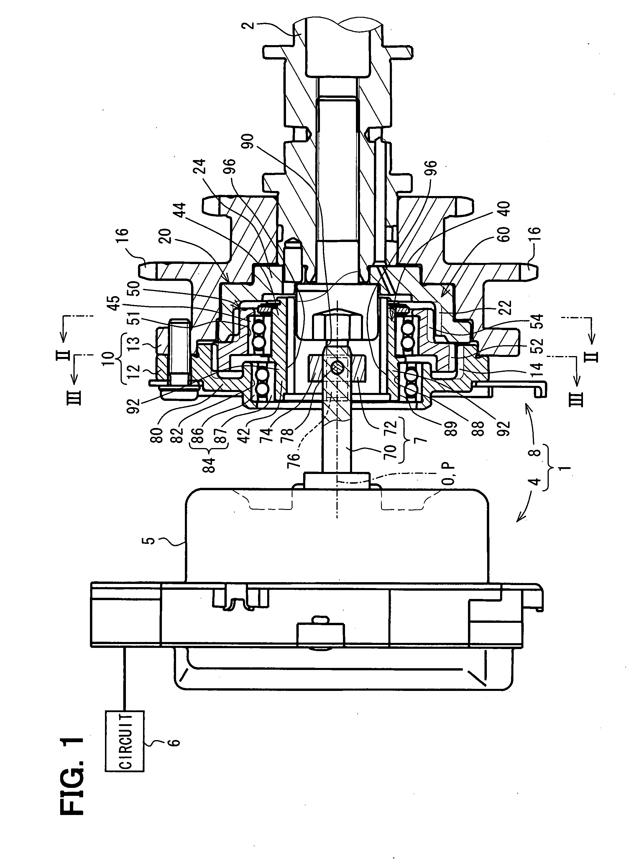
[0021]FIG. 1 shows the valve timing controller 1 according to a first embodiment of the present invention. The valve timing controller 1 is provided in the transmission system which transmits engine torque to the camshaft 2 from the crankshaft (not shown) of the internal combustion engine. The valve timing controller 1 includes a torque generating system 4 and a phase adjusting mechanism 8, and adjusts the engine phase between the crankshaft and the camshaft 2. In the present embodiment, the camshaft 2 opens / closes the intake valve (not shown), and the valve timing controller 1 adjusts the valve timing of the intake valve.

[0022]First, the torque generating system 4 is explained. The torque generating system 4 is provided with an electric motor 5 and a control circuit 6.

[0023]The electric motor 5 is, for example, a brushless motor, and generates a controlling torque on a shaft 7 when energized. The control circuit 6 includes a microcomputer and a motor driver, and is arranged in exte...

second embodiment

[0046]As shown in FIG. 7, in the input wall 100 of a second embodiment, the width W2 and the depth D2 of the inner concave portion 104 which form each thin-wall portion 102 are substantially equal to the width W0 and the depth D0 of the fitting recess 90, respectively. Therefore, as shown by two-dot chain line in FIG. 7, even if each projected part 76 is erroneously inserted into the inner concave portion 104, these concave portions 104 can be operated as the fitting recess 90.

third embodiment

[0047]As shown in FIG. 8, in a third embodiment of this invention, each thin-wall part 154 is formed by denting and curving the inner surface 152 of the input wall 150 outwardly in a radial direction. Therefore, the projected part 76 is prevented from erroneously being inserted into a portion other than fitting recess 90 of the input wall 150.


PUM


Abstract

A valve timing controller has a shaft body as an output rotor, a torque generating system which generates the controlling torque outputted from the shaft body, and a planet carrier as an input rotor connected with the shaft body. A phase adjusting mechanism adjusts the relative rotational phase between a crankshaft and a camshaft according to the control torque inputted into the planet carrier from the shaft body. A bearing rotatably supports the planet carrier. The planet carrier forms a cylindrical input wall press-inserted in an inner circumference of the bearing. The input wall is provided with a fitting recess on its inner surface for engaging with the shaft body, the input wall is provided with a thin-wall portion of which thickness is reduced in a radial direction, and the fitting recess and the thin-wall portion are circumferentially arranged apart from each other.

Description

CROSS-REFERENCE TO RELATED APPLICATION[0001]This application is based on Japanese Patent Application No. 2006-275515 filed on Oct. 6, 2006, the disclosure of which is incorporated herein by reference.FIELD OF THE INVENTION[0002]The present invention relates to a valve timing controller which adjusts valve timing of an inlet valve and / or an exhaust valves of an internal combustion engine.BACKGROUND OF THE INVENTION[0003]A valve timing controller adjusts the relative rotational phase (engine phase) between a crankshaft and a camshaft which determines valve timing by using the controlling torque generated by a torque generation means, such as an electric motor and a dynamo-electric brake.[0004]In such a valve timing controller, an output rotor is connected to an input rotor of a phase adjusting mechanism. The output rotor outputs a control torque, and the phase adjusting mechanism adjusts the engine phase. That is, the engine phase is adjusted according to the control torque which is t...

Claims


Application Information

Patent Timeline
Patent Type & Authority Applications(United States)
IPC IPC(8): F16D3/10
CPCF01L1/352F16C35/067F01L2820/032
Inventor SUGIURA, TAEIMORII, YASUSHI
Owner DENSO CORP
Learn More