Rotary type combined press

A rotary, press technology, applied in metal processing, metal processing equipment, manufacturing tools, etc., can solve the problems of low efficiency, poor product consistency, small press space, etc., and achieve the effect of rapid use

Inactive Publication Date: 2018-05-29
ZHEJIANG WELL SHINE IND & TRADE CO LTD
View PDF0 Cites 1 Cited by
  • Summary
  • Abstract
  • Description
  • Claims
  • Application Information

AI Technical Summary

Problems solved by technology

[0002] In the garden machinery or electric tool industry, the bearings have been press-fitted in the left and right boxes of the pressing box, and the crankshaft assembly needs to be pressed into the left and right boxes. After the press-fitting is completed, the left and right boxes need to be locked with screws. Small, after the pressing is completed, the product needs to be taken out and taken to another tooling to lock the screws, which is inefficient, resulting in a lot of waste of action, and the product consistency is poor

Method used


Image

  • Rotary type combined press
  • Rotary type combined press
  • Rotary type combined press

Examples


Embodiment Construction

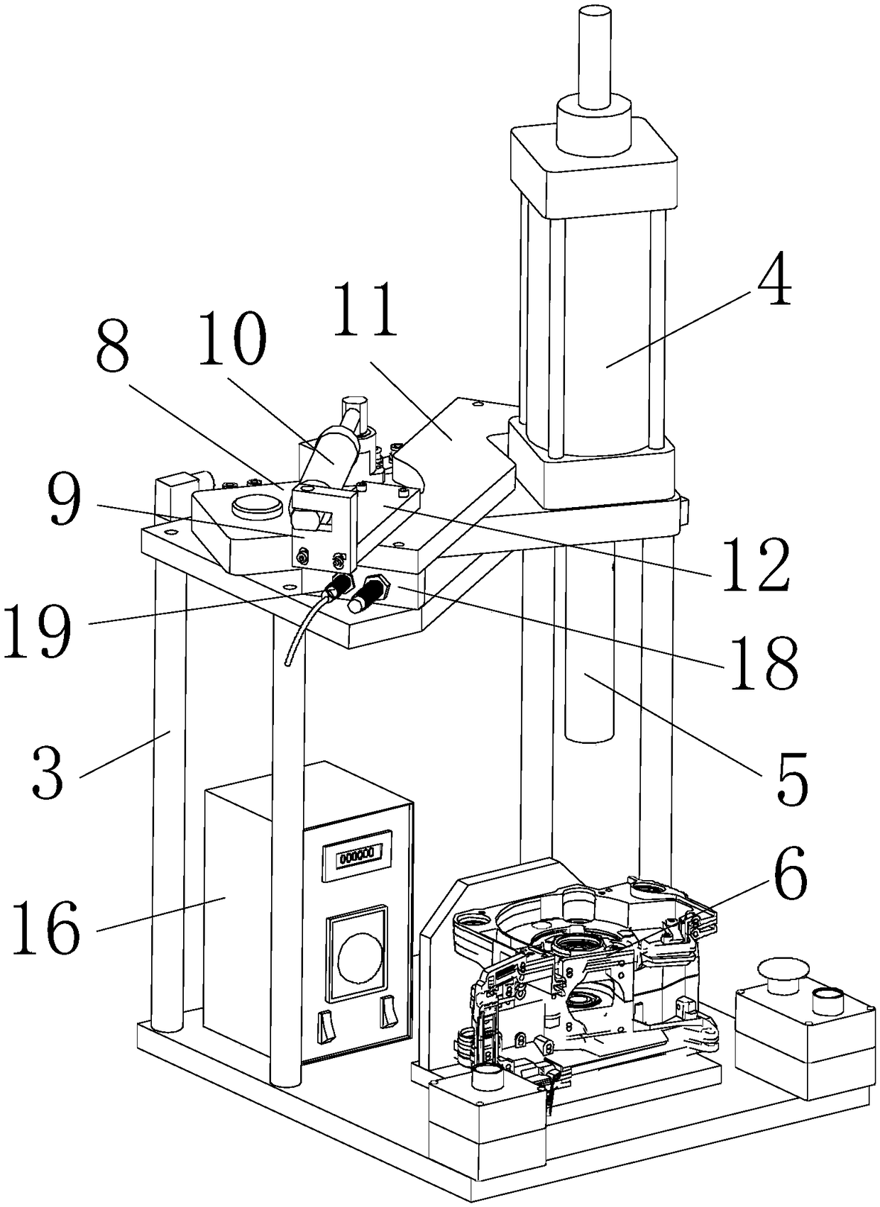
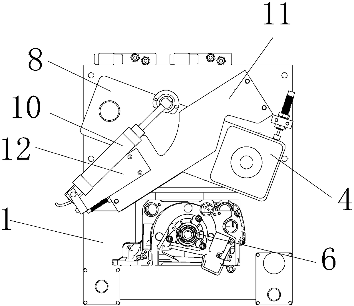
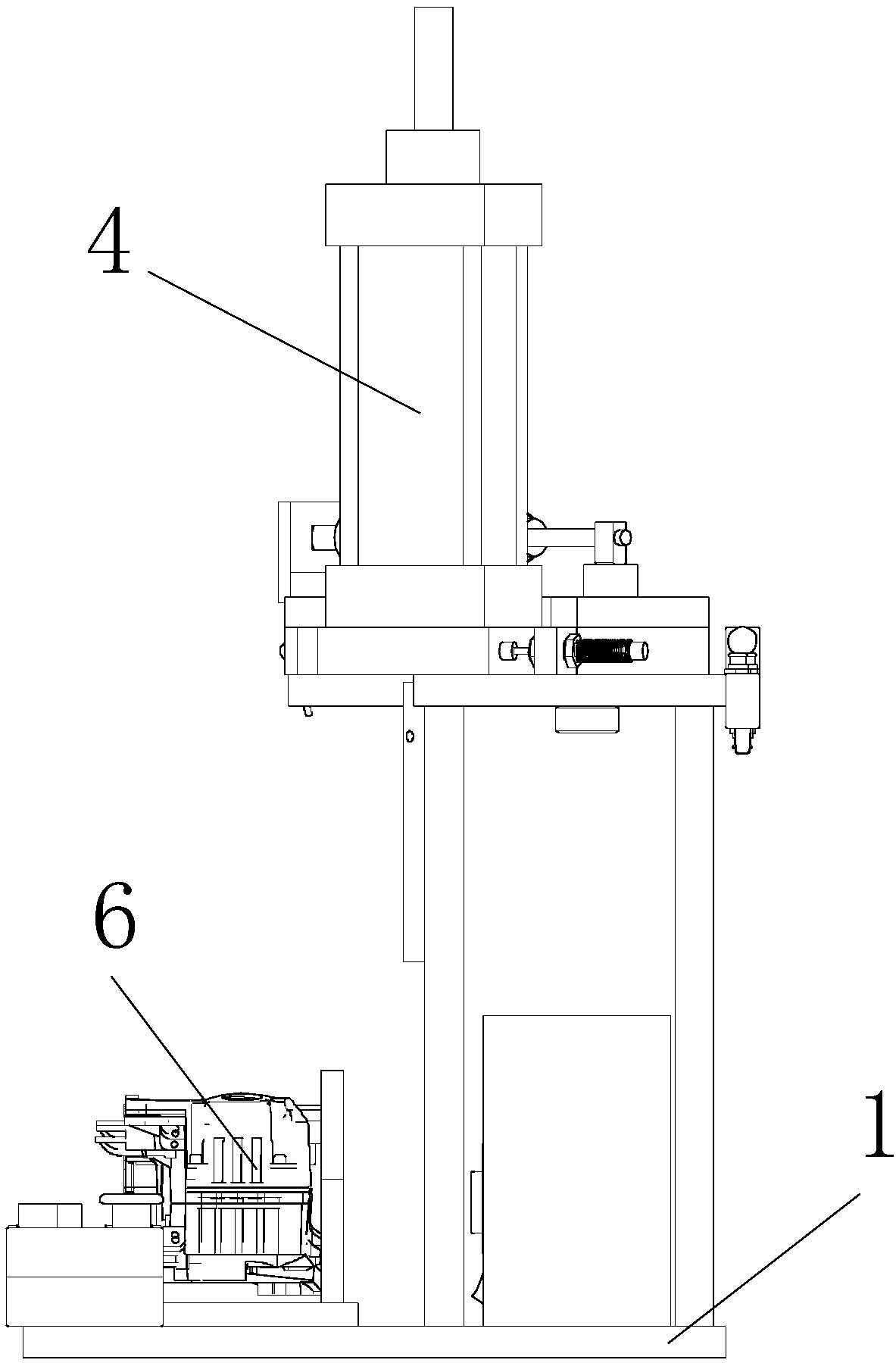
[0033] With reference to the accompanying drawings, a rotary combination press includes a horizontally laid bottom plate 1, the bottom plate 1 includes a front half and a rear half, the upper surface of the front half is provided with a placement for stamping parts for stamping Position 6; a top plate 2 is erected on the upper surface of the second half, the top plate 2 is parallel to the bottom plate 1, and the placement position is outside the projection of the top plate 2 on the bottom plate 1 (that is, the top plate 2 is not Covering the placement position 6); the stamping cylinder 4 for stamping to the placement position 6 is rotatably arranged on the top plate 2 through a rotating device;

[0034] Described rotating device comprises the main board 8 that is laid horizontally on the upper surface of top board 2, and described main board 8 is rotatably arranged on top board 2, and the left end of described main board 8 is hinged with a corner of the left rear side of top bo...


PUM


Abstract

A rotary type combined press comprises a bottom plate which is laid horizontally, wherein the bottom plate comprises a front half portion and a rear half portion; a placement position for placement ofa stamping part for stamping is arranged on the upper surface of the front half portion; a top plate is erected on the upper surface of the rear half portion; the top plate is parallel to the bottomplate; the placement position is located out of the projection of the top plate on the bottom plate; a stamping cylinder for stamping the placement position is rotatably arranged on the top plate through a rotating device; the rotating device comprises a main plate which is horizontally laid on the upper surface of the top plate; the rotating device further comprises a pressure plate which is parallel to the main plate and is intersected with the main plate; and an adjusting cylinder for driving the main plate to rotate is arranged between the left end of the pressure plate and the left end ofthe main plate. A proximity switch which is used for detecting whether the main plate rotates to a second position or not is arranged on the side, which faces the main plate, of a connecting seat positioned at the left end, and the proximity switch, the stamping cylinder and the adjusting cylinder are connected with a controller.

Description

technical field [0001] The invention relates to a rotary combination press. Background technique [0002] In the garden machinery or electric tool industry, the bearings have been press-fitted in the left and right boxes of the pressing box, and the crankshaft assembly needs to be pressed into the left and right boxes. After the press-fitting is completed, the left and right boxes need to be locked with screws. Small, after the pressing is completed, the product needs to be taken out and taken to another tooling to lock the screws, which is inefficient, resulting in a lot of waste of action, and the product consistency is poor. Contents of the invention [0003] In order to overcome the above problems, the present invention provides a rotary combination press. [0004] To achieve the above object, the present invention adopts the following technical solutions: [0005] A rotary combination press, comprising a horizontally laid bottom plate, the bottom plate includes a fr...

Claims


Application Information

Patent Timeline
Patent Type & Authority Applications(China)
IPC IPC(8): B23P19/027
CPCB23P19/027
Inventor 陈曦陈元福钱法桂吴盛雄于胜伦宋亚琼胡训周刘远兵
Owner ZHEJIANG WELL SHINE IND & TRADE CO LTD
Why Eureka
Try Eureka