Single-motor 360-degree all-dimensional shuttle type towel device
An all-round, single-motor technology, applied in the direction of embroidery machine, embroidery machine mechanism, textile and papermaking, etc., can solve the problems of increasing the weight of the embroidery head, increasing the cost of the embroidery head, increasing the power consumption of other components, etc. The volume and weight of the machine head, the effect of improving space utilization and reducing consumption
- Summary
- Abstract
- Description
- Claims
- Application Information
AI Technical Summary
Problems solved by technology
Method used
Image
Examples
Embodiment 1
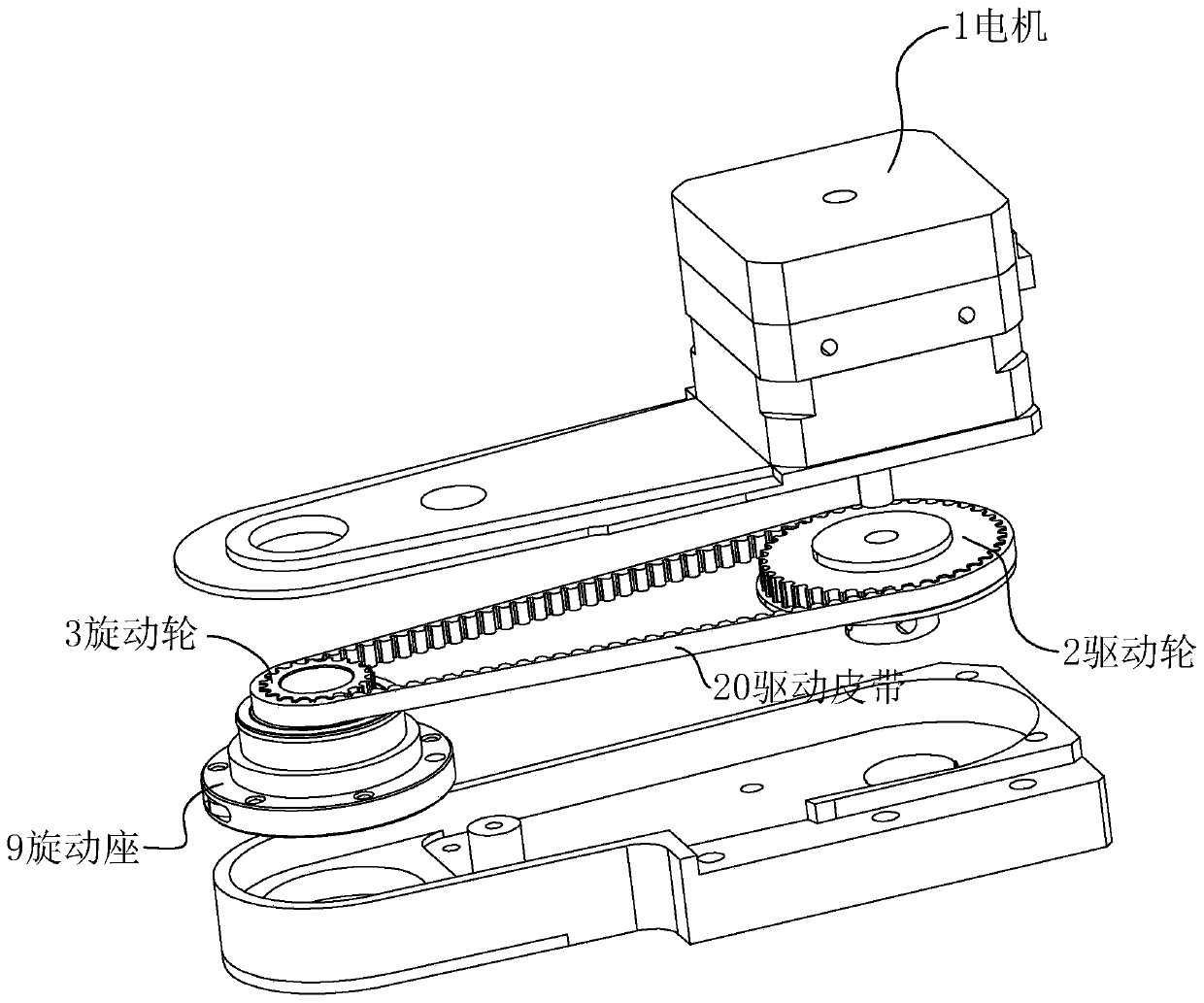
[0058] Such as Figures 1 to 10 The shown single-motor 360-degree omni-directional shuttle towel device includes a swing needle 6, a rotary seat 9, a driving source 1, a transmission mechanism and a linkage mechanism.
[0059] Such as figure 1 and Figure 5 As shown, in the first embodiment, the driving source 1 adopts one motor. The transmission mechanism includes a drive wheel 2 , a drive belt 20 , a rotary wheel 3 and a drive shaft 4 .
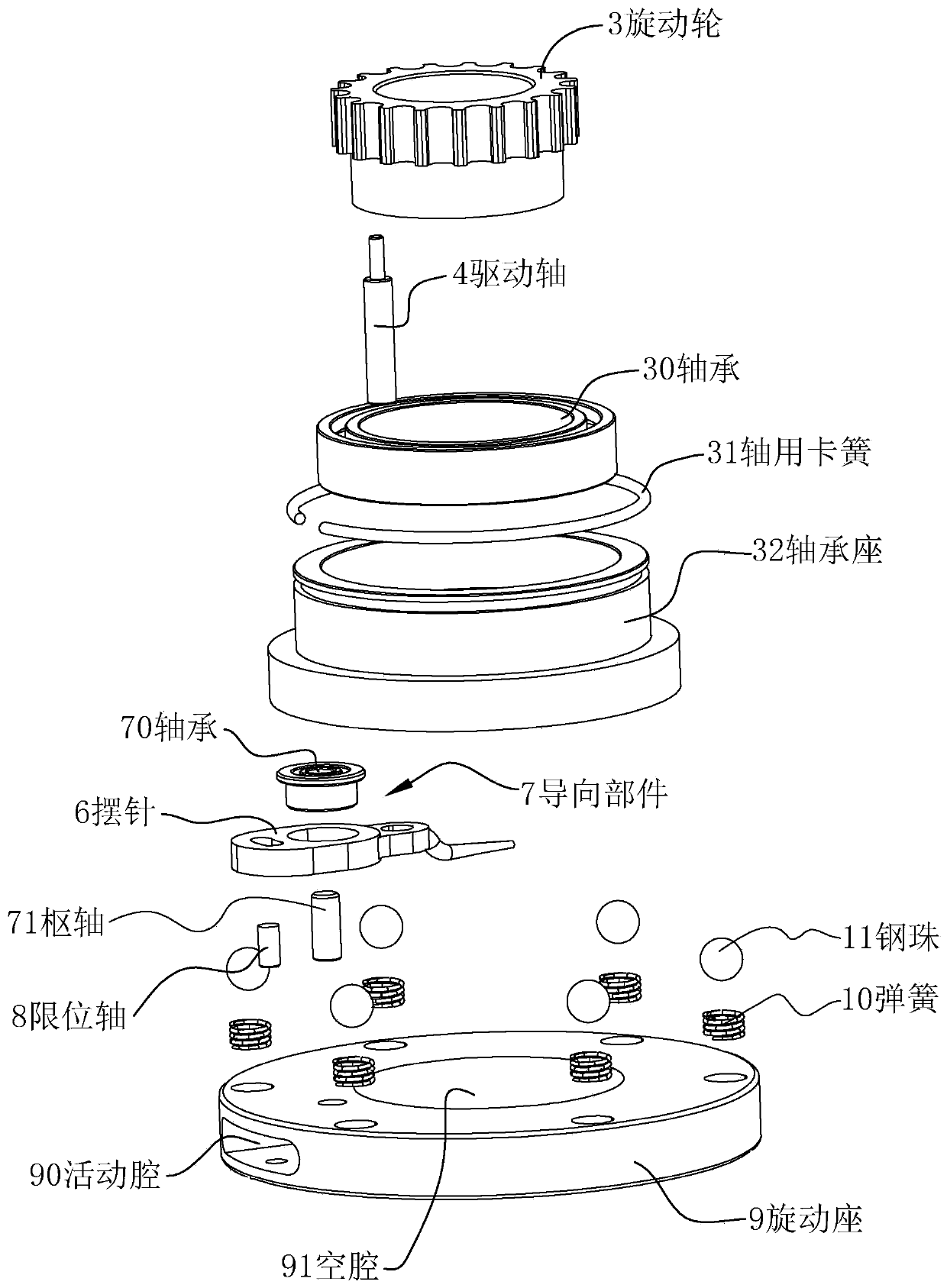
[0060] The linkage mechanism includes a swing path 63 , a guide part 7 and a limiting part 8 , the guiding part 7 is a pivot 71 , and the limiting part 8 is rod-shaped.
[0061] Such as figure 2 As shown, the middle part of the rotary seat 9 is provided with a cavity 91 for the embroidery machine needle 116 to shuttle, the rotary seat 9 can rotate along the center of the cavity 91, and the top of the rotary seat 9 is a bearing seat 32 and a bearing 30. The rotary wheel 3 is fixed on the bearing inner ring. The rotation axis of the s...
Embodiment 2
[0078] Such as Figure 11 As shown, the difference between this implementation and Embodiment 1 is that the guiding mechanism and linkage mechanism in this embodiment are different from those in Embodiment 1.
[0079] In this embodiment, the guide mechanism includes a guide swing rod 71a, a guide swing post 70a and a limit swing rod 8a.
[0080] Two guide pendulums 70a are arranged on the surface of the pendulum needle 6, and two limit pendulums 8a are arranged on the swivel seat 9, and the limit pendulum 8a and the guide pendulum 70a are connected through the guide pendulum 71a, so that the pendulum needle 6 and the guide pendulum 70a are connected. A parallelogram is formed between the swivel seats 9 .
[0081] Therefore the pendulum needle 6 swing of this embodiment can refer to Figure 11 (a1), (a2) (a3), so as to realize the operation of "coil toggle". The pendulum needle 6 is also in the same plane during the swing process, and the flatness of the obtained coil is the...
Embodiment 3
[0084] Such as Figure 12 As shown, the difference between this implementation and Embodiment 1 is that the guiding mechanism and linkage mechanism in this embodiment are different from those in Embodiment 1.
[0085] In this embodiment, the guide mechanism includes a guide rail 7b, and the linkage mechanism includes a limiting outer edge 8b and a baffle.
[0086] The swivel seat 9 is provided with two above-mentioned guide rails 7b, and the baffles are located at both ends of the guide rails 7b (corresponding to the end of the path).
[0087] The middle part of the swing needle 6 cooperates with the guide rail 7b, and can move back and forth on the guide rail 7b, such as Figure 12 (b1) and (b2), so as to realize the operation of "coil toggling", the pendulum needle 6 is also in the same plane during the swing process, and the flatness of the produced coil is the same as that of Example 1.
[0088] And when the driving end 61 moves to the limit of the swing path 63a toward ...
PUM
 Abstract
Description
Claims
Application Information
 - R&D
- Intellectual Property
- Life Sciences
- Materials
- Tech Scout
- Unparalleled Data Quality
- Higher Quality Content
- 60% Fewer Hallucinations
Browse by: Latest US Patents, China's latest patents, Technical Efficacy Thesaurus, Application Domain, Technology Topic, Popular Technical Reports.
© 2025 PatSnap. All rights reserved.Legal|Privacy policy|Modern Slavery Act Transparency Statement|Sitemap|About US| Contact US: help@patsnap.com


