
Reservoir floating garbage cleaning device

A technology for garbage cleaning and reservoir, which is applied in the direction of open water surface cleaning, water conservancy engineering, construction, etc., can solve the problems of large labor, long time consumption, short time consumption

Inactive Publication Date: 2018-05-29
饶胜智
View PDF6 Cites 27 Cited by
  • Summary
  • Abstract
  • Description
  • Claims
  • Application Information

AI Technical Summary

Problems solved by technology

[0005] In order to overcome the shortcomings of the traditional hand-held salvage equipment, such as poor cleaning effect, long time consumption, and large manpower required, the technical problem to be solved by the present invention is to provide a device that can salvage garbage on the water surface by itself. , a reservoir floating garbage cleaning device with good cleaning effect and short time consumption

Method used


Image

  • Reservoir floating garbage cleaning device
  • Reservoir floating garbage cleaning device
  • Reservoir floating garbage cleaning device

Examples


Embodiment 1

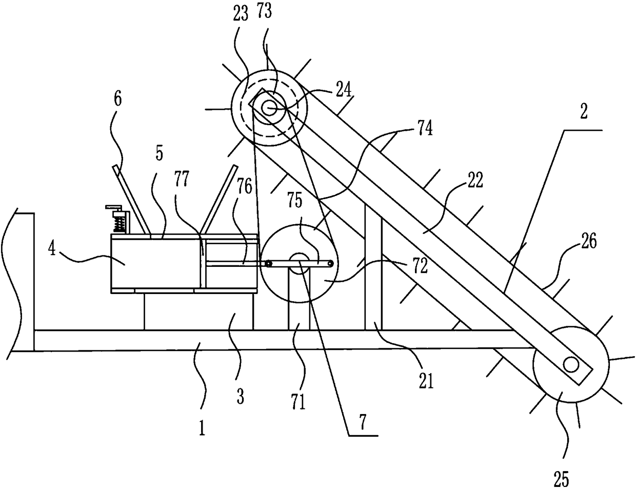
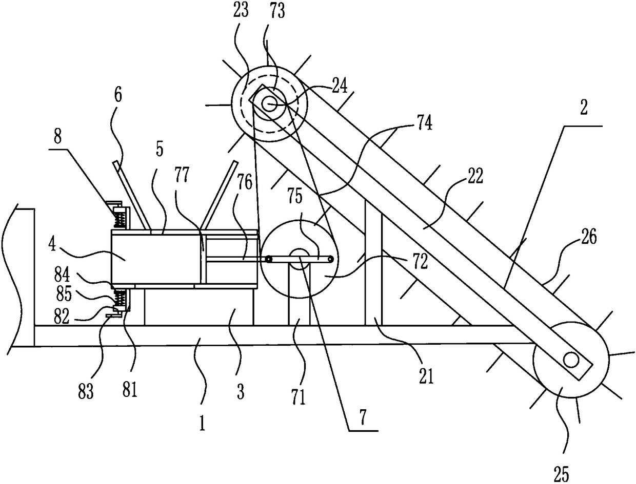
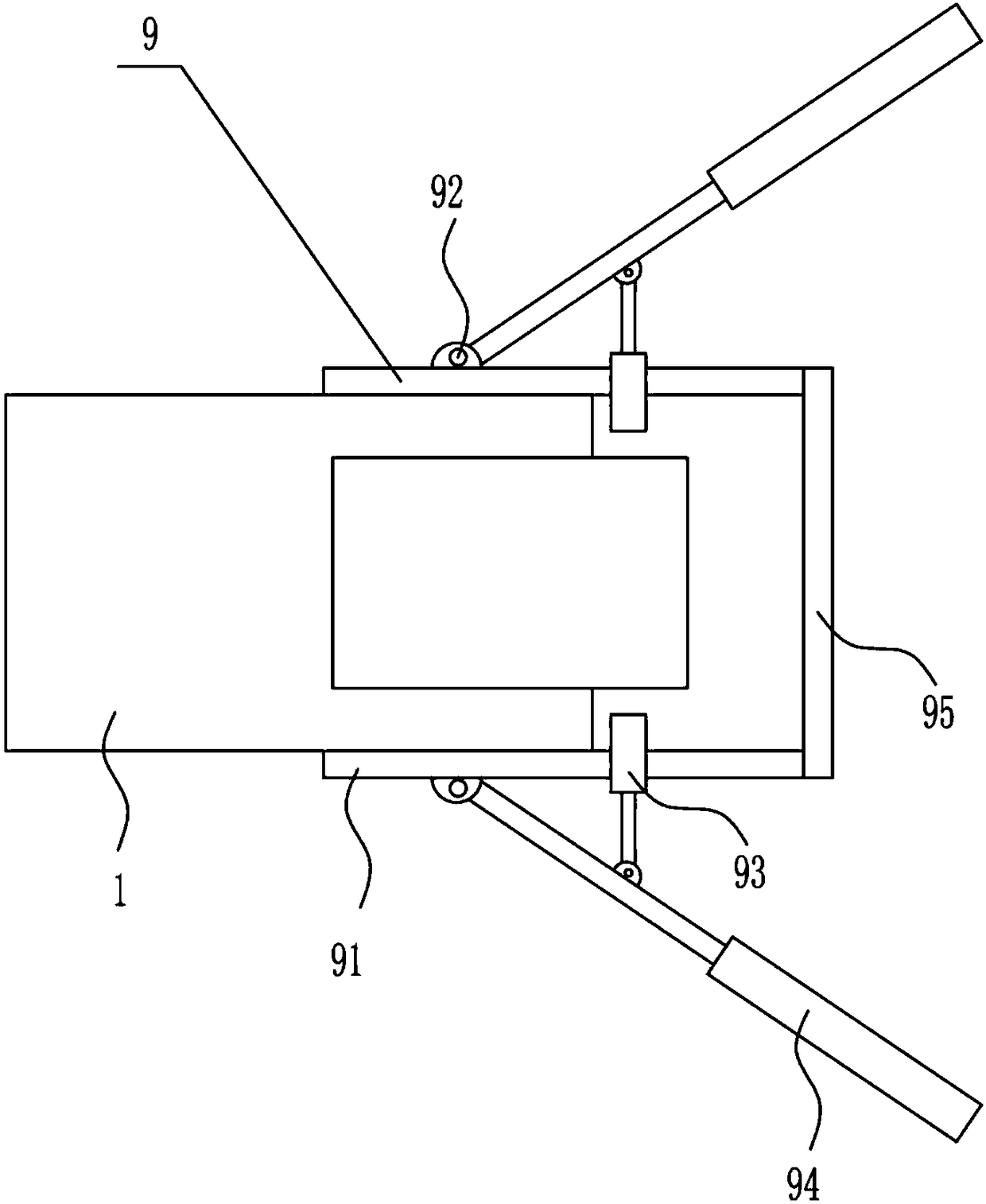
[0030] A kind of reservoir floating rubbish cleaning device, such as Figure 1-4 As shown, include floating plate 1, salvage mechanism 2, second fixed plate 3, compression pipe 4, feed inlet 5, guide plate 6 and compression mechanism 7 The right side of floating plate 1 top is equipped with salvage mechanism 2, floating plate 1 The left side of the top is provided with a second fixed plate 3, the top of the second fixed plate 3 is provided with a compression tube 4, the top of the compression tube 4 has a feed port 5, and the top of the compression tube 4 has a feed port 5 position The left and right sides of the floating plate 1 are symmetrically connected with guide plates 6, and the top of the floating plate 1 is equipped with a compression mechanism 7.

Embodiment 2

[0032] A kind of reservoir floating rubbish cleaning device, such as Figure 1-4 As shown, include floating plate 1, salvage mechanism 2, second fixed plate 3, compression pipe 4, feed inlet 5, guide plate 6 and compression mechanism 7 The right side of floating plate 1 top is equipped with salvage mechanism 2, floating plate 1 The left side of the top is provided with a second fixed plate 3, the top of the second fixed plate 3 is provided with a compression tube 4, the top of the compression tube 4 has a feed port 5, and the top of the compression tube 4 has a feed port 5 position The left and right sides of the floating plate 1 are symmetrically connected with guide plates 6, and the top of the floating plate 1 is equipped with a compression mechanism 7.

[0033]The fishing mechanism 2 includes a first support rod 21, a first fixed plate 22, a motor 23, a first rotating shaft 24, a drum 25 and a brush belt 26, and the right side of the top of the floating plate 1 is vertical...

Embodiment 3

[0035] A kind of reservoir floating rubbish cleaning device, such as Figure 1-4 As shown, include floating plate 1, salvage mechanism 2, second fixed plate 3, compression pipe 4, feed inlet 5, guide plate 6 and compression mechanism 7 The right side of floating plate 1 top is equipped with salvage mechanism 2, floating plate 1 The left side of the top is provided with a second fixed plate 3, the top of the second fixed plate 3 is provided with a compression tube 4, the top of the compression tube 4 has a feed port 5, and the top of the compression tube 4 has a feed port 5 position The left and right sides of the floating plate 1 are symmetrically connected with guide plates 6, and the top of the floating plate 1 is equipped with a compression mechanism 7.

[0036] The fishing mechanism 2 includes a first support rod 21, a first fixed plate 22, a motor 23, a first rotating shaft 24, a drum 25 and a brush belt 26, and the right side of the top of the floating plate 1 is vertica...


PUM


Abstract

The invention relates to hydraulic engineering treatment equipment, in particular to a reservoir floating garbage cleaning device and aims at achieving the technical purpose of providing the reservoirfloating garbage cleaning device which can automatically fish garbage on the water surface and is good in cleaning effect and short in consumed time. To achieve the technical purpose, the reservoir floating garbage cleaning device comprises a floating plate and the like, the left side of the top of the floating plate is provided with a second fixing plate, the top of the second fixing plate is provided with a compression pipe, the top of the compression pipe is provided with a feed port, the left side and the right side of the position, providing with the feed port, of the top of the compression pipe are symmetrically connected with guide plates, and the top of the floating plate is provided with a compression mechanism. According to the reservoir floating garbage cleaning device, by means of mutual coordination of a fishing mechanism and the compression mechanism, fishing and compression treatment is carried out on the garbage on the water surface, meanwhile, by means of the optimization of a fixing mechanism and a gathering mechanism, the effects that the garbage on the water surface is automatically fished, the cleaning effect is good, and the consumed time is short are achieved.

Description

technical field [0001] The invention relates to water conservancy treatment equipment, in particular to a device for cleaning floating garbage in reservoirs. Background technique [0002] Water conservancy is a Chinese term that means the development of water resources and the prevention of floods or water conservancy projects. The quotations and explanations come from "Lushi Chunqiu Shenren" and so on. [0003] Large-scale reservoirs have a certain amount of garbage floating on the water surface due to environmental factors. How to clean up these garbage has become a major problem in the maintenance of the reservoir. However, the cleaning effect of traditional hand-held salvage equipment is poor and takes a long time. The labor required is relatively large, so there is an urgent need to develop a reservoir floating garbage cleaning device that can salvage the garbage on the water surface by itself, has a good cleaning effect, and takes a short time. Contents of the inven...

Claims


Application Information

Patent Timeline
Patent Type & Authority Applications(China)
IPC IPC(8): E02B15/10
CPCE02B15/10E02B15/104
Inventor 饶胜智陈星李蓓
Owner 饶胜智
Learn More