A continuously variable valve lift hydraulic tappet mechanism for an engine

A technology of valve lift and hydraulic tappet, applied in the direction of engine components, machines/engines, mechanical equipment, etc., can solve the problems of partially lifting the engine, high production cost, and inconvenient layout

Active Publication Date: 2020-07-07
GUIZHOU GEELY ENGINE CO LTD +1
View PDF5 Cites 0 Cited by
  • Summary
  • Abstract
  • Description
  • Claims
  • Application Information

AI Technical Summary

Problems solved by technology

A class of variable valve lift devices in the prior art belongs to graded adjustment, and the valve lift of this type of device can be adjusted from two to three levels, but the disadvantage is that it can only partially improve the performance of the engine; although the other type can Realize the continuous variable valve lift, but there are problems such as complex structure, high production cost, and inconvenient arrangement in the small space of the engine

Method used


Image

  • A continuously variable valve lift hydraulic tappet mechanism for an engine
  • A continuously variable valve lift hydraulic tappet mechanism for an engine
  • A continuously variable valve lift hydraulic tappet mechanism for an engine

Examples


Embodiment 1

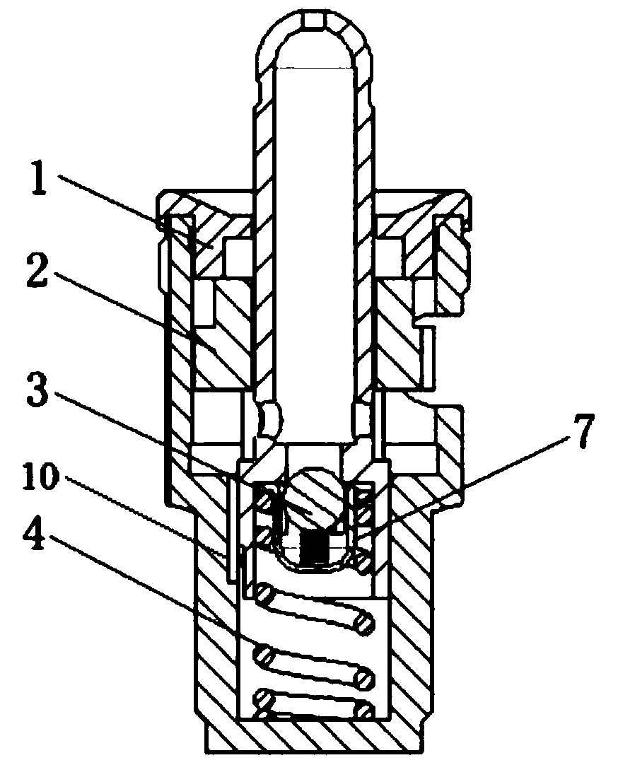
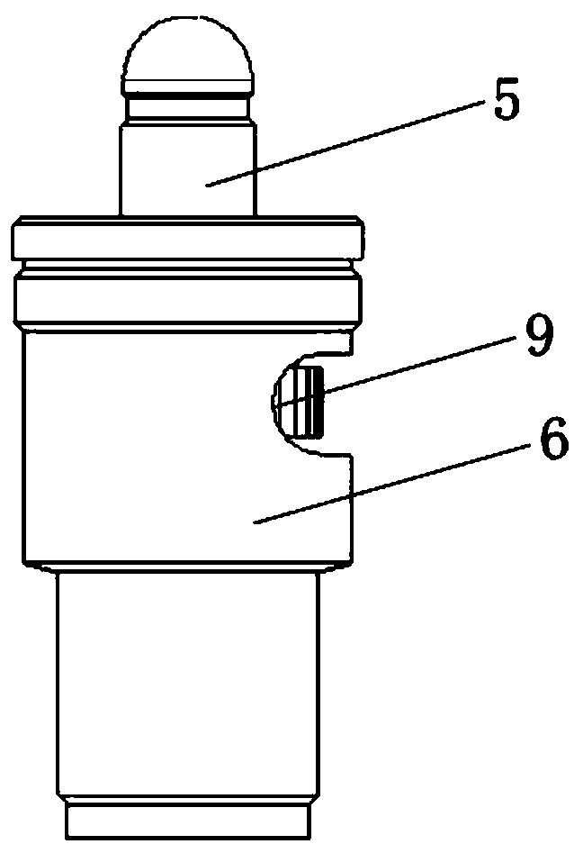
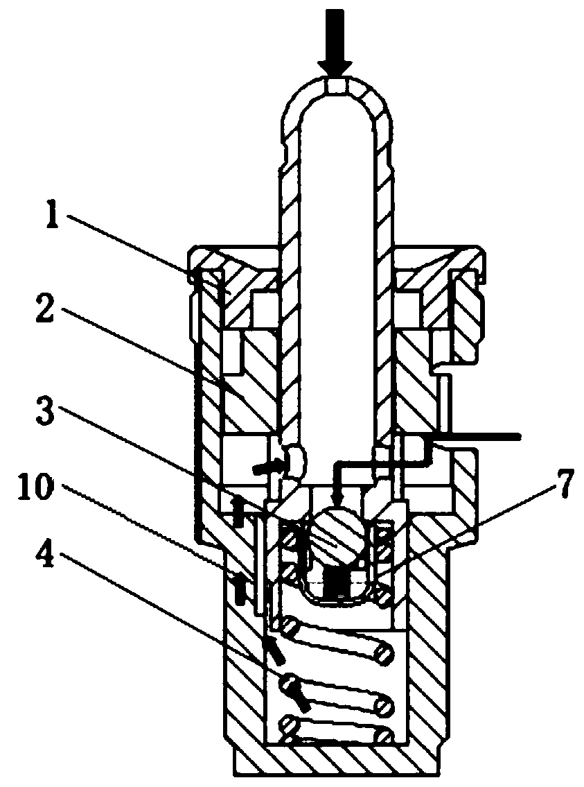
[0026] see figure 1 and figure 2 , This embodiment provides an engine continuously variable valve lift (CVHLA) hydraulic tappet mechanism, including an upper cover 1, a control wheel 2, a one-way valve 3, a return spring 4, a control valve rod 5 and a housing 6.

[0027] Wherein, the upper end cover 1 is threadedly connected with the casing 6 , and the casing 6 is provided with an oil drain channel and a groove 9 .

[0028] The control wheel 2 is arranged inside the housing 6. The control wheel 2 has an incomplete gear structure, and its angle is controlled by a rack. In this embodiment, the diameter of the control wheel 2 is 16 mm.

[0029] The center of the control wheel 2 is provided with a central hole, and the control valve rod 5 is passed through the central hole.

[0030] The one-way valve 3 is arranged at the bottom end of the control valve stem 5, and the outside of the one-way valve 3 is provided with a piston 7. In this embodiment, the diameter of the piston 7 is...

Embodiment 2

[0036] see figure 1 and figure 2 , This embodiment provides an engine continuously variable valve lift (CVHLA) hydraulic tappet mechanism, including an upper cover 1, a control wheel 2, a one-way valve 3, a return spring 4, a control valve rod 5 and a housing 6.

[0037] Wherein, the upper end cover 1 is threadedly connected with the casing 6 , and the casing 6 is provided with an oil drain channel and a groove 9 .

[0038] The control wheel 2 is arranged inside the housing 6. The control wheel 2 has an incomplete gear structure, and its angle is controlled by a rack. In this embodiment, the diameter of the control wheel 2 is 14 mm.

[0039] The center of the control wheel 2 is provided with a central hole, and the control valve rod 5 is passed through the central hole.

[0040]The one-way valve 3 is arranged at the bottom end of the control valve rod 5, and the outside of the one-way valve 3 is provided with a piston 7. In this embodiment, the diameter of the piston 7 is 8...


PUM


Abstract

The invention discloses a hydraulic tappet mechanism with an engine valve lift being continuously variable. The hydraulic tappet mechanism comprises a control wheel, a one-way valve, a return spring,a control valve rod and a shell. The shell is installed on the outer portion of the control wheel in a sleeving mode, an oil drainage channel is formed in the shell, the control wheel is arranged on the control valve rod in a sleeving mode, the one-way valve is arranged at the bottom end of the control valve rod, and a piston is arranged on the outer portion of the one-way valve; and the piston isin contact with the return spring, a control area is formed on the piston, when the control valve rod is at different angles, the positions of the control area are different, adjustment of differentpressure relief heights can be achieved, and the engine valve lift is finally changed. According to the hydraulic tappet mechanism, the oil drainage lift of a hydraulic tappet is adjusted through a mechanical mode, so that the situation that the engine valve lift is continuously variable is achieved, the structure is simple, and arrangement in an engine cylinder head is easy.

Description

technical field [0001] The invention relates to the technical field of engine valves, in particular to an engine continuously variable valve lift hydraulic tappet mechanism. Background technique [0002] Since the 21st century, with the continuous increase of car ownership, the problems of environmental pollution and energy shortage caused by cars have become increasingly prominent, and the development of high-efficiency, energy-saving and environmentally friendly cars is imminent. In the face of strict emission regulations and fuel economy requirements, automobiles are the main bearers of energy-saving and emission-reduction technologies, and automobile manufacturers have developed a series of energy-saving and emission-reduction technologies for automobiles. Among them, variable technology can better reduce engine fuel consumption because it can optimize the structure or parameters of engine-related systems under different operating conditions. As a technology that can im...

Claims


Application Information

Patent Timeline
Patent Type & Authority Patents(China)
IPC IPC(8): F01L1/245
CPCF01L1/245
Inventor 张明东马瑞博蒋恩杰李连豹韦虹李军王瑞平
Owner GUIZHOU GEELY ENGINE CO LTD
Why Eureka
Try Eureka