A camshaft-based continuously variable valve lift electronically controlled hydraulic adjustment mechanism

A valve lift and electronically controlled hydraulic technology, which is applied in mechanical equipment, engine components, machines/engines, etc., can solve the problems of large flow inertia, small flow inertia, and fixedness, etc., to overcome complex structure and few mechanism parts , the effect of taking up little space

Inactive Publication Date: 2017-03-01
ZHONGBEI UNIV
View PDF4 Cites 0 Cited by
  • Summary
  • Abstract
  • Description
  • Claims
  • Application Information

AI Technical Summary

Problems solved by technology

[0002] The engine realizes the ventilation process through the valve mechanism, and its speed changes in a relatively large range during the working process: when the engine is running at low speed, the airflow speed is slow, the flow inertia is small, and the valve lift is too large to cause the fresh air in the cylinder to flow back; when the engine is running at high speed , the airflow speed is faster, the flow inertia is larger, and the valve lift that is too small will increase the flow resistance, which is also not conducive to the perfection of the intake process
In order to overcome the shortcomings of the fixed valve lift of the traditional engine valve train and the shortcomings of the existing variable valve lift device, an electro-hydraulic adjustment mechanism based on the camshaft with continuously variable valve lift is proposed here

Method used


Image

  • A camshaft-based continuously variable valve lift electronically controlled hydraulic adjustment mechanism
  • A camshaft-based continuously variable valve lift electronically controlled hydraulic adjustment mechanism

Examples


Embodiment Construction

[0016] specific implementation plan

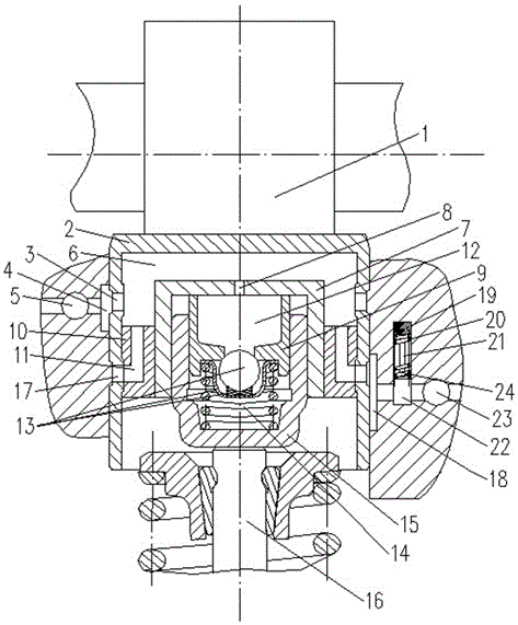
[0017] A continuously variable valve lift hydraulic adjustment mechanism, including a tappet body (2), a cam (1) linked to the tappet body, an oil inlet groove (4) connecting the main oil passage of the engine with an oil inlet hole, and an oil adjustment chamber (6), the sliding sleeve (7), the oil hole (8), the plunger connected with the valve (9), the oil drain channel (11), the one-way valve (13), the connection The oil return channel (23) of the engine, the oil return groove (18) of the oil return hole (17), and the control valve body (24), in which the sliding sleeve (7) is connected with the plunger sleeve (15) and the plunger (9) to form a The auxiliary oil chamber (12) and the high-pressure oil chamber (14), and the check valve (13) is located inside the high-pressure oil chamber to isolate the auxiliary oil chamber (12) and the high-pressure oil chamber (14).

[0018] The tappet (2) is in contact with the outer edge of the engin...


PUM


Abstract

The invention provides an electronically controlled hydraulic adjustment mechanism with continuously variable valve lift based on a camshaft, the structure includes a cam, a tappet, an oil inlet hole, a main oil passage of an engine body, an adjustment oil cavity, a sliding sleeve, an oil hole, Plunger, connecting body, oil drain channel, one-way valve, plunger sleeve, air valve, oil return hole, oil return groove, solenoid valve, return spring, guide rod, control piston, oil return channel, wherein the tappet follows the cam Move along the outer edge of the sliding sleeve, and adjust the oil pressure in the oil chamber to act on the top surface of the sliding sleeve. The sliding sleeve moves up and down along the inner edge of the connecting body and the outer edge of the plunger sleeve. The plug encloses an auxiliary oil chamber and a high-pressure oil chamber, and the bottom of the plunger sleeve is connected with the valve head. The beneficial effect is that by controlling the oil in and out, and adjusting the valve lift by adjusting the oil volume change in the oil chamber, the valve lift can be continuously variable. The deficiency of the existing regulating mechanism is overcome.

Description

technical field [0001] The invention relates to the field of an engine valve mechanism, in particular to an electronically controlled hydraulic adjustment mechanism based on a camshaft whose valve lift is continuously variable. Background technique [0002] The engine realizes the ventilation process through the valve mechanism, and its speed changes in a relatively large range during the working process: when the engine is running at low speed, the airflow speed is slow, the flow inertia is small, and the valve lift is too large to cause the fresh air in the cylinder to flow back; when the engine is running at high speed , the airflow speed is faster, the flow inertia is larger, and the valve lift that is too small will increase the flow resistance, which is also not conducive to the perfection of the intake process. In order to overcome the shortcomings of the fixed valve lift of the traditional engine valve train and the shortcomings of the existing variable valve lift de...

Claims


Application Information

Patent Timeline
Patent Type & Authority Patents(China)
IPC IPC(8): F01L13/00F01L9/02F01L9/11F01L9/40
CPCF01L13/00F01L9/10
Inventor 王艳华冯耀南刘汉涛普永王英
Owner ZHONGBEI UNIV
Why Eureka
Try Eureka