Valve pressure detection machine

A valve pressure and detection machine technology, applied in the direction of measuring device, fluid tightness test, machine/structural component test, etc., can solve problems such as low efficiency, low detection accuracy, gas leakage, etc., and achieve the degree of automation high effect

Pending Publication Date: 2018-05-29
沪航科技集团有限公司
3 Cites 0 Cited by

AI-Extracted Technical Summary

Problems solved by technology

[0002] The valves in the prior art usually need to be tested for air tightness, that is, the valve is first opened by the valve stem, injected with high-pressure gas and then passed through, the valve stem is operated to cl...

Abstract

The invention provides a valve pressure detection machine which is high in automation degree and improves detection efficiency. The valve pressure detection machine comprise a rack, a workpiece base,a sliding clamping base, a first driving mechanism, a rotating sleeve, an ejector block, a positioning hole, a reset air cylinder and a second driving mechanism, wherein the workpiece base is fixedlyarranged on the rack; the sliding clamping base is arranged above the workpiece base in a sliding mode in the vertical direction and is matched with the workpiece base; the first driving mechanism isused for driving the sliding clamping base to slide, and the rotating sleeve is rotationally arranged on the rack; the ejector block is arranged in the rotating sleeve and only slides in the axis direction of the rotating sleeve, and the positioning hole is formed in the ejector block; the reset air cylinder drives the ejector block to reset, and the second driving mechanism drives the rotating sleeve to rotate; the rotation axis of the rotating sleeve is perpendicular to the sliding direction of the sliding clamping base.

Application Domain

Measurement of fluid loss/gain rate

Technology Topic

EngineeringAutomation +1

Image

  • Valve pressure detection machine
  • Valve pressure detection machine

Examples

  • Experimental program(1)

Example Embodiment

[0015] The specific embodiments of the present invention will be further described below in conjunction with the drawings and embodiments. The following embodiments are only used to explain the technical solutions of the present invention more clearly, and cannot be used to limit the protection scope of the present invention.
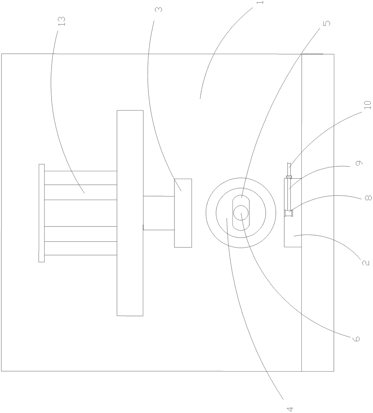
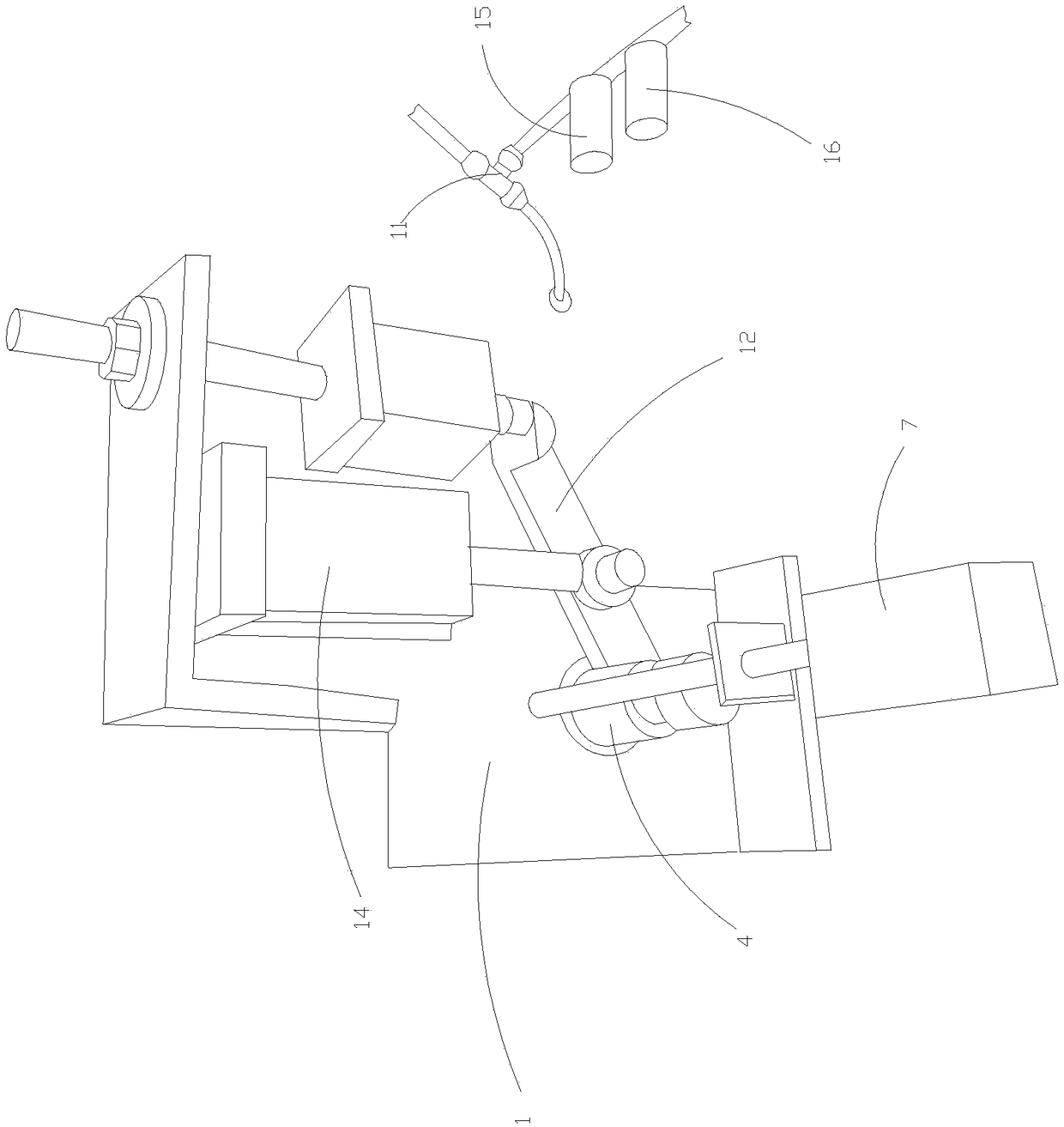
[0016] Such as figure 1 , figure 2 As shown, a valve pressure testing machine includes a frame 1, a workpiece base fixedly arranged on the frame 1, a sliding clamp base 3 slidably arranged above the workpiece base 2 in a vertical direction and matched with it , The first drive mechanism that drives the sliding clamp base 3 to slide, rotates the rotating sleeve 4 arranged on the frame 1, and only slides on the rotating sleeve 4 along the axis of the rotating sleeve 4 The inner top block 5, the positioning hole 6 opened on the top block 5, the reset cylinder 7 that drives the top block 5 to reset, the second driving mechanism that drives the rotation sleeve 4 to rotate, the rotation sleeve 4 The axis of rotation is perpendicular to the sliding direction of the sliding clamp base 3;
[0017] The workpiece base 2 is provided with a gas nozzle 8 and a connector 9 communicating with the gas nozzle 8. The connector 9 communicates with a gas pipe 10, and the gas pipe 10 is provided with a solenoid valve 11;
[0018] The second driving mechanism includes a swing rod 12 fixedly connected to the rotating sleeve 4 at one end, a second driving cylinder 14 for driving the swing rod 12 to rotate, and a piston rod of the second driving cylinder 14 is connected to the The middle part of the pendulum rod 12 is rotatably connected, and the other end of the pendulum rod 12 is a free end;
[0019] The frame 1 is also provided with a first limit sensor 15 and a second limit sensor 16 for detecting the position of the top block 5.
[0020] The first limit sensor 15, the second limit sensor 16 are connected to the controllers of the first drive cylinder 13, the second drive cylinder 14, the reset cylinder 7, and the solenoid valve 11 on the air pipe 10, and pass the first limit The sensor 15 and the second limit sensor 16 detect the position of the top block 5 so as to open or close accordingly.
[0021] Working process: Place the detected valve on the workpiece base 2 so that the gas nozzle 8 is aligned with the valve. The valve stem is inserted into the positioning hole 6 of the top block 5. When the valve stem is inserted, the top block 5 is pushed to move, and the limit sensor senses After that, the first drive mechanism drives the sliding clamp seat 3 to position the valve, the second drive mechanism drives the rotating sleeve 4 to rotate, and then drives the valve stem to turn to open the valve and start to inject gas. After completion, the second drive mechanism drives the valve stem to reset , The valve is closed, and the reset cylinder 7 pushes the top block 5 out, and the limit sensor senses to reset the first driving mechanism and the solenoid valve 11 on the gas pipe 10, and the valve can be removed with a high degree of automation.
[0022] The preferred implementation in this embodiment is that the first drive mechanism is a first drive cylinder 13, the cylinder of the first drive cylinder 13 is fixed on the frame 1, and the first drive cylinder 13 The piston rod is fixedly connected with the sliding clamp base 3.
[0023] The preferred implementation in this embodiment is that a push slider is slidably provided in the rotating sleeve 4, a spring is provided between the top block 5 and the push slider, and the piston rod of the reset cylinder 7 is connected to The top block 5 is fixedly connected, and the cylinder body of the reset cylinder 7 is fixed on the frame 1 through a first tie rod.
[0024] The preferred implementation in this embodiment is that the frame 1 is also provided with a limit cylinder, the cylinder of the limit cylinder is fixed to the frame 1 through a second tie rod, and the swing rod 12 is free The end conflicts with the piston rod of the limiting cylinder.
[0025] The basic principles, main features and advantages of the present invention are shown and described above. Those skilled in the industry should understand that the present invention is not limited by the above-mentioned embodiments. The above-mentioned embodiments and descriptions only illustrate the principles of the present invention. Without departing from the spirit and scope of the present invention, the present invention will have various changes and improvements. These changes and improvements fall within the scope of the claimed invention. The scope of the claimed invention is determined by the appended claims. And its equivalent definition.

PUM

no PUM

Description & Claims & Application Information

We can also present the details of the Description, Claims and Application information to help users get a comprehensive understanding of the technical details of the patent, such as background art, summary of invention, brief description of drawings, description of embodiments, and other original content. On the other hand, users can also determine the specific scope of protection of the technology through the list of claims; as well as understand the changes in the life cycle of the technology with the presentation of the patent timeline. Login to view more.

Similar technology patents

System and method for forecasting molten steel components in RH refining process in online manner

InactiveCN103382514AGuaranteed Reasonableness and Accuracyhigh degree of automation
Owner:NORTHEASTERN UNIV +1

Flexible production system for micro die casting fitting grinding detection

ActiveCN110385618AImprove flexible production and management levelhigh degree of automation
Owner:CHONGQING INST OF GREEN & INTELLIGENT TECH CHINESE ACADEMY OF SCI

Plastic bag in-half folding bagging machine

Owner:安徽银生电气设备有限公司

Classification and recommendation of technical efficacy words

Why Eureka
Try Eureka