Wire stripping and wrapping machine

A stand-alone, wire-stripping technology, applied in the direction of line/collector parts, cable installation devices, electrical components, etc., can solve the problems of manual mechanical devices such as high labor intensity, difficult quality assurance, and low work efficiency, so as to save manpower and material resources , quality and stability, and the effect of improving production efficiency

Inactive Publication Date: 2018-05-29
新昌县七星街道同亨模具厂
View PDF0 Cites 2 Cited by
  • Summary
  • Abstract
  • Description
  • Claims
  • Application Information

AI Technical Summary

Problems solved by technology

[0002] At present, there are already wire stripping and sheet punching technologies, and there are many areas that need to be improved, such as low wor...

Method used


Image

  • Wire stripping and wrapping machine

Examples


Embodiment Construction

[0011] Embodiments of the present invention will be described in further detail below in conjunction with the accompanying drawings.

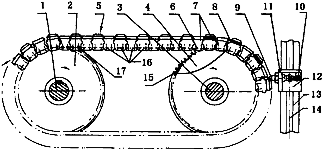
[0012] This embodiment provides a wire stripping punching machine, characterized in that: the wire stripping punching machine includes a driving shaft 1, a driving wheel 2, a driven shaft 3, a driven wheel 4, a conveyor belt 5, a chain 6, and a wire fixing block 7. Lead wire 8, wire inlet tube 9, lead wire guide wheel 10, bracket 11, slider 12, support 13, slideway 14, locking teeth 15, wire stripping 16, punching sheet 17; among them: there is a fixed wire on the conveyor belt 5 Block 7, fixed wire block 7 is used for clamping wire 8, and driving wheel 2 is installed on the driving shaft (1), and driven wheel 4 is installed on the driven shaft 3, and driving wheel 2 and driven wheel 4 are the sprockets that are shaped on teeth 15 , The junction of the conveyor belt 5 and the sprocket is a chain 6 .

[0013] The driving wheel 2 and the driven ...


PUM


Abstract

The invention provides a wire stripping and wrapping machine which is characterized by comprising a driving shaft, a driving wheel, a driven shaft, a driven wheel, a conveying belt, a chain, wire fixing blocks, a lead, a wire inlet tube, a lead guide wheel, a support, a slide block, a slideway, clamp teeth, wire stripping mechanisms and wire wrapping mechanisms. The driving wheel is installed on the driving shaft. The driven wheel is installed on the driven shaft. The wire fixing blocks are installed on the conveying belt. The driving wheel and the driven wheel are the chain wheels provided with teeth. The combining part of the conveying belt and the chain wheels is provided with the chain of which the two sides are provided with the wire stripping mechanisms and the wire wrapping mechanisms. The wire stripping mechanisms and the wire wrapping mechanisms are matched with the operation lead. The advantages of the wire stripping and wrapping machine are that the wire stripping and wrapping machine is enabled to perform mechanically continuous, efficient and high-quality production work.

Description

technical field [0001] The invention relates to a wire stripping and punching equipment, in particular to a fully automatic wire stripping and punching machine. Background technique [0002] At present, there are wire stripping and sheet punching technologies, and there are many areas to be improved, such as low work efficiency, difficult quality assurance, single function, poor versatility, unsafe belt production, manual mechanical devices and labor-intensive defects. Contents of the invention [0003] The purpose of the present invention is to overcome the deficiencies of the prior art, to provide a fully automatic wire stripping punching machine, to improve efficiency, ensure quality, reduce labor intensity, reduce labor costs and reduce costs. [0004] The technical solution adopted by the present invention to solve the problems of the technologies described above is: [0005] A wire stripping punching machine, characterized in that: the wire stripping punching machin...

Claims


Application Information

Patent Timeline
IPC IPC(8): H02G1/12H01R43/28
CPCH02G1/1248H01R43/28
Inventor 杨怡
Owner 新昌县七星街道同亨模具厂
Why Eureka
Try Eureka