Photocuring 3D printing device and printing method

A 3D printing and light curing technology, applied in the field of 3D printing, can solve the problems of low printing efficiency, printing Z-axis accuracy (layer thickness accuracy deviation, affecting printing accuracy, etc., to improve the molding efficiency and shorten the waiting time effect.

Active Publication Date: 2018-06-01
BMF NANO MATERIAL TECH CO LTD
View PDF6 Cites 5 Cited by
  • Summary
  • Abstract
  • Description
  • Claims
  • Application Information

AI Technical Summary

Benefits of technology

This technology helps improve the speed at which liquids are applied during manufacturing processes while reducing wait times between when they start being filled with solvents or other fluids before reaching their final destination.

Problems solved by technology

This patented describes different ways how microscopic three dimensional structures may be printed on surfaces like plates used in various industries such as electronics, optics, biology, medicine, etc., but they all require some type of material called photopolymerizable resins. These materials have unique characteristics that allow them to harden quickly without leaving any residue behind from their own chemical reaction. By controllably adding more layers onto top of these resists before being fully solidified, precise levels can be achieved over longer periods of time compared to traditional techniques. Additionally, if the printer has multiple print modes - either mode requiring separate steps between two successive stages or allowing only one stage per second, then slowdown times caused by relying upon gravity to keep the remaining part still remain constant could lead to errors in printing results.

Method used


Image

  • Photocuring 3D printing device and printing method
  • Photocuring 3D printing device and printing method
  • Photocuring 3D printing device and printing method

Examples


Embodiment Construction

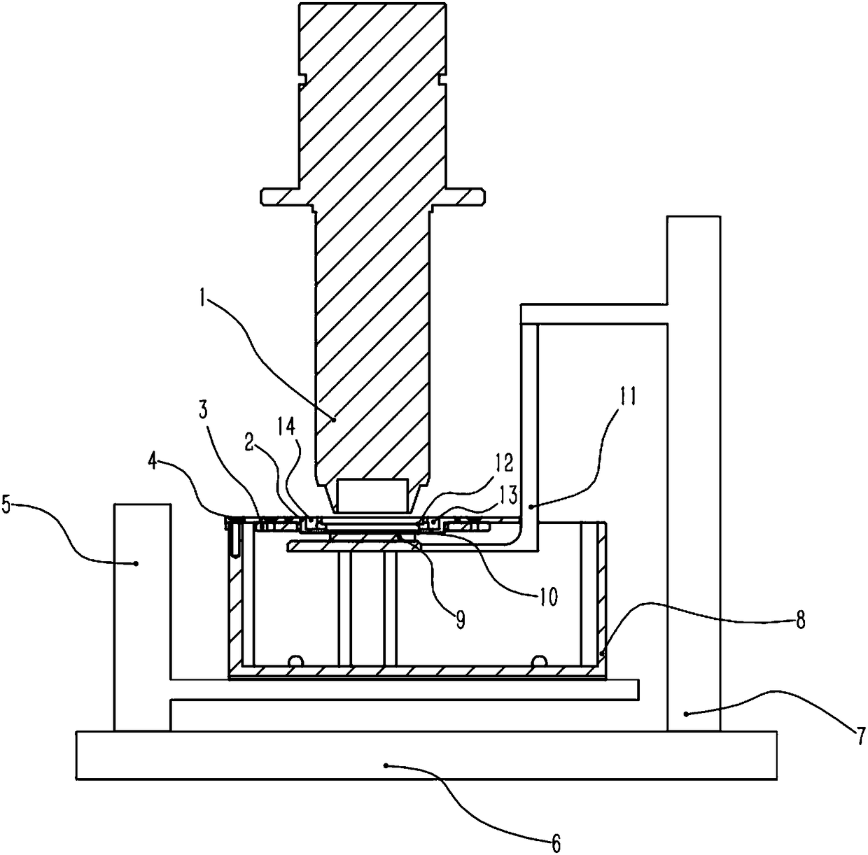
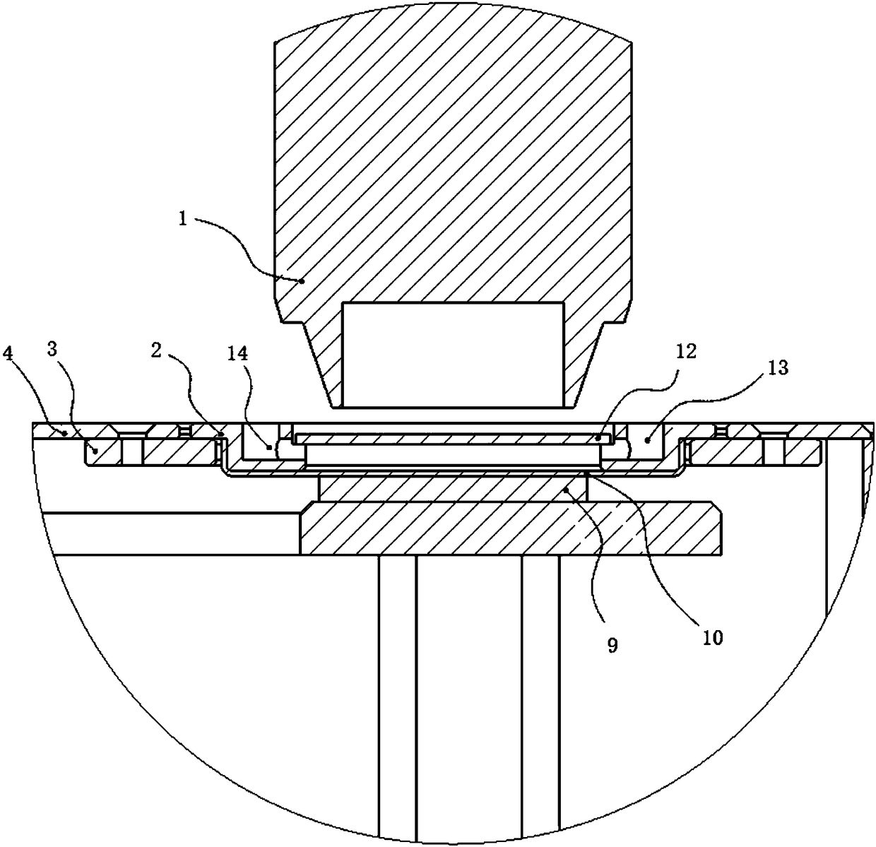
[0028] Such as Figure 1 to Figure 2 As shown, the present invention discloses a light-curing 3D printer, including a liquid tank 8, a liquid tank lifting mechanism 5, a printing platform 11 and a printing platform lifting mechanism 7, the printing platform 11 is placed in the liquid tank 8, and the The upper end of the liquid tank 8 is provided with a film-immersing mechanism, the film-immersing mechanism includes a stretch film mechanism and an immersion film 10 fixed on the stretch film mechanism, the printing platform 11 is located at the lower end of the immersion film 10, and the liquid Resin materials for printing products are housed in the groove 8, and a silicon chip 9 is arranged on the printing platform 11, and the silicon chip 9 corresponds to the position of the immersion film 10, and the immersion film 10 is immersed in the place by a stretch film mechanism. In this way, the resin layer above the silicon wafer 9 on the printing platform 11 can be compressed and l...


PUM


Abstract

The invention provides a photocuring 3D printing device and a printing method. The photocuring 3D printing device comprises a liquid tank, a liquid tank lifting mechanism, a printing platform and a printing platform lifting mechanism. The printing platform is disposed in the liquid tank, a membrane immersing mechanism is arranged at the upper end of the liquid tank and comprises a membrane stretching mechanism and an immersed membrane fixed on the membrane stretching mechanism, and the printing platform is located at the lower end of the immersed membrane. By arranging the membrane immersing mechanism, resin at the upper end of the printing platform can be oppressed for leveling through the immersed membrane immersed in the resin, the waiting time of leveling of a liquid level is greatly shortened, and the forming efficiency is improved.

Description


Claims


Application Information

Patent Timeline
Owner BMF NANO MATERIAL TECH CO LTD
Why Eureka
Try Eureka