
More stable lifting mechanism

A lifting mechanism and a stable technology, applied in the field of a more stable lifting mechanism, can solve the problems of unstable lifting, difficulty in adjusting the lifting stroke, poor adjustment accuracy of the lifting mechanism, etc., achieving strong adjustability, convenient adjustment, and wide applicability of equipment. Effect

Inactive Publication Date: 2018-06-01
无锡博硕精睿科技有限公司
View PDF8 Cites 4 Cited by
  • Summary
  • Abstract
  • Description
  • Claims
  • Application Information

AI Technical Summary

Problems solved by technology

[0002] In the production line of traditional photovoltaic modules, the transmission height between devices often changes. To facilitate the realization of functions in a certain device, it is often necessary to raise or lower certain parts of the device to avoid interference with other mechanisms. The traditional lifting mechanism has disadvantages such as poor adjustment accuracy, difficulty in adjusting the lifting stroke, and unstable lifting.

Method used


Image

  • More stable lifting mechanism
  • More stable lifting mechanism

Examples


Embodiment Construction

[0015] The technical solutions in the embodiments of the present invention will be clearly and completely described below in conjunction with the accompanying drawings in the embodiments of the present invention. Obviously, the described embodiments are only a part of the embodiments of the present invention, rather than all the embodiments. Based on the embodiments of the present invention, all other embodiments obtained by those of ordinary skill in the art without creative work shall fall within the protection scope of the present invention.

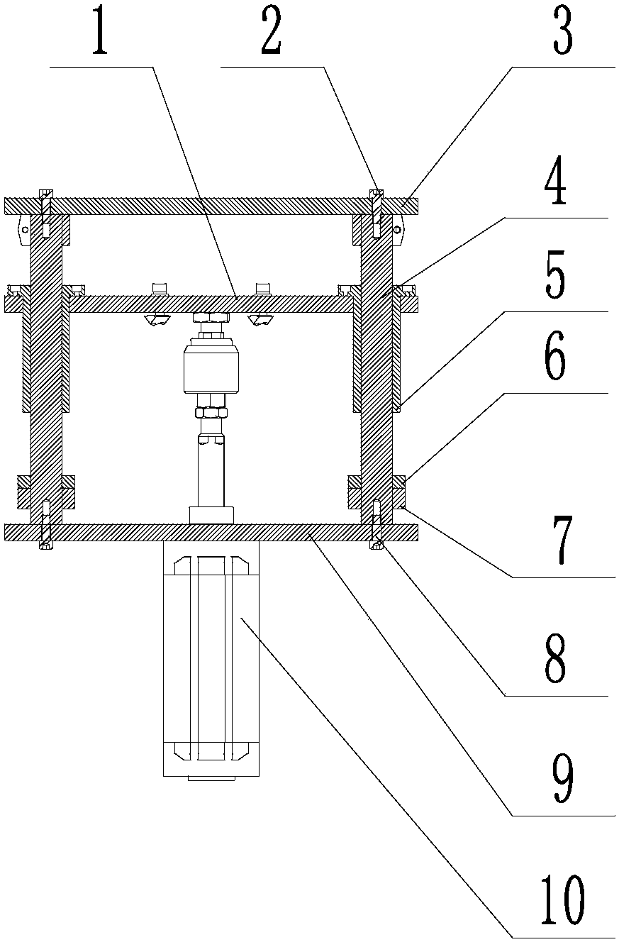
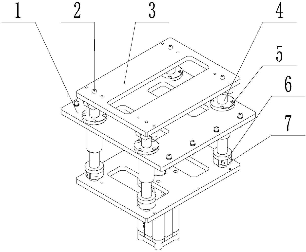
[0016] See Figure 1-2 , The present invention provides the following technical solutions: a more stable lifting mechanism, including linear bearing mounting plate 1, component connecting plate 3, linear optical axis 4, linear bearing 5, buffer seat 6, clamp 7, cylinder mounting plate 9 and Cylinder 10, the upper end of the cylinder 10 is provided with a cylinder mounting plate 9, the upper middle of the cylinder mounting plate 9 is prov...


PUM


Abstract

The invention discloses a more stable lifting mechanism. The lifting mechanism comprises a linear bearing mounting plate, a component connecting plate, LM shafts, linear bearings, buffer seats, clamping hoops, an air cylinder mounting plate and an air cylinder, wherein the air cylinder mounting plate is arranged at the upper end of the air cylinder, the four corners of the upper portion of the aircylinder mounting plate are provided with the LM shafts, the clamping hoops are arranged on the circumference of the LM shafts above the air cylinder mounting plate, the buffer seats are arranged onthe clamping hoops, the linear bearing mounting plate is arranged at the middle positions of the LM shafts, and the linear bearings are arranged at the joints of the linear bearing mounting plate andthe LM shafts and located at the outer side of the circumference of the LM shafts. The more stable lifting mechanism has the beneficial effects that the LM shafts are connected and fastened with the upper mounting plate and the lower mounting plate of the lifting mechanism, so that the lifting process is guaranteed to be stable, accurate and horizontal; and the stroke of the lifting mechanism canbe conveniently adjusted through a clamping hoop fixing structure, so that the mechanism is wider in applicability and stronger in adjustability.

Description

Technical field [0001] The invention belongs to the technical field of lifting equipment, and specifically relates to a more stable lifting mechanism. Background technique [0002] In the assembly line body of traditional photovoltaic module manufacturing, the transmission height between equipment often changes. To facilitate the realization of functions in a certain equipment, it is often necessary to raise or lower certain parts of the equipment to avoid interference with other institutions. Traditional lifting mechanisms have disadvantages such as poor adjustment accuracy, difficulty in adjusting the lifting stroke, and uneven lifting. Summary of the invention [0003] The purpose of the present invention is to provide a more stable lifting mechanism to solve the above-mentioned background art problems. [0004] In order to achieve the above objective, the present invention provides the following technical solutions: a more stable lifting mechanism, including a linear bearing mo...

Claims


Application Information

Patent Timeline
Patent Type & Authority Applications(China)
IPC IPC(8): B65G47/57
CPCB65G47/57
Inventor 韩忠侯伟李岩
Owner 无锡博硕精睿科技有限公司
Learn More