
Adsorption buffer

A buffer device and moving shaft technology, which is applied in the direction of transportation and packaging, conveyor objects, conveyors, etc., can solve the problems of positioning accuracy degradation, dust falling, and trouble

Active Publication Date: 2019-11-12
CKD
View PDF5 Cites 0 Cited by
  • Summary
  • Abstract
  • Description
  • Claims
  • Application Information

AI Technical Summary

Problems solved by technology

It is very troublesome to connect the adsorption pad holder and the rotating shaft of the motor while aligning the axis of the rotating shaft of the motor with the axis of the movable shaft.
In addition, there are problems such as concerns that the positioning accuracy will deteriorate due to dust generated by the operation, or that the dust may fall to the transfer surface, etc.

Method used


Image

  • Adsorption buffer
  • Adsorption buffer
  • Adsorption buffer

Examples


Embodiment Construction

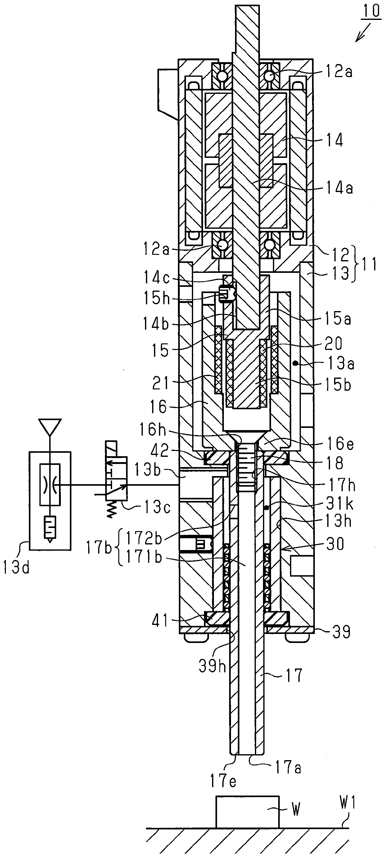
[0032] Follow the figure 1˜ FIG. 7 illustrate an embodiment of the present invention in which an adsorption buffer device is embodied. The suction cushioning device of this embodiment suctions objects to be conveyed, such as electronic components. In addition, the suction cushioning device is used attached to the tip of an XYZ actuator not shown.

[0033] like figure 1 As shown, the housing 11 of the suction cushioning device 10 has a motor housing 12 and a cylindrical main body housing 13 connected to the motor housing 12 . A rotor 14 of the electric motor is housed in the motor housing 12 , and the rotor 14 has a rotating shaft 14 a. The main body case 13 is coupled to the motor case 12 such that the axial direction of the main body case 13 coincides with the axial direction of the rotary shaft 14a.

[0034] The rotating shaft 14a is rotatably supported by the motor case 12 via the bearing 12a. Both ends of the rotating shaft 14 a pass through the motor case 12 and pr...


PUM


Abstract

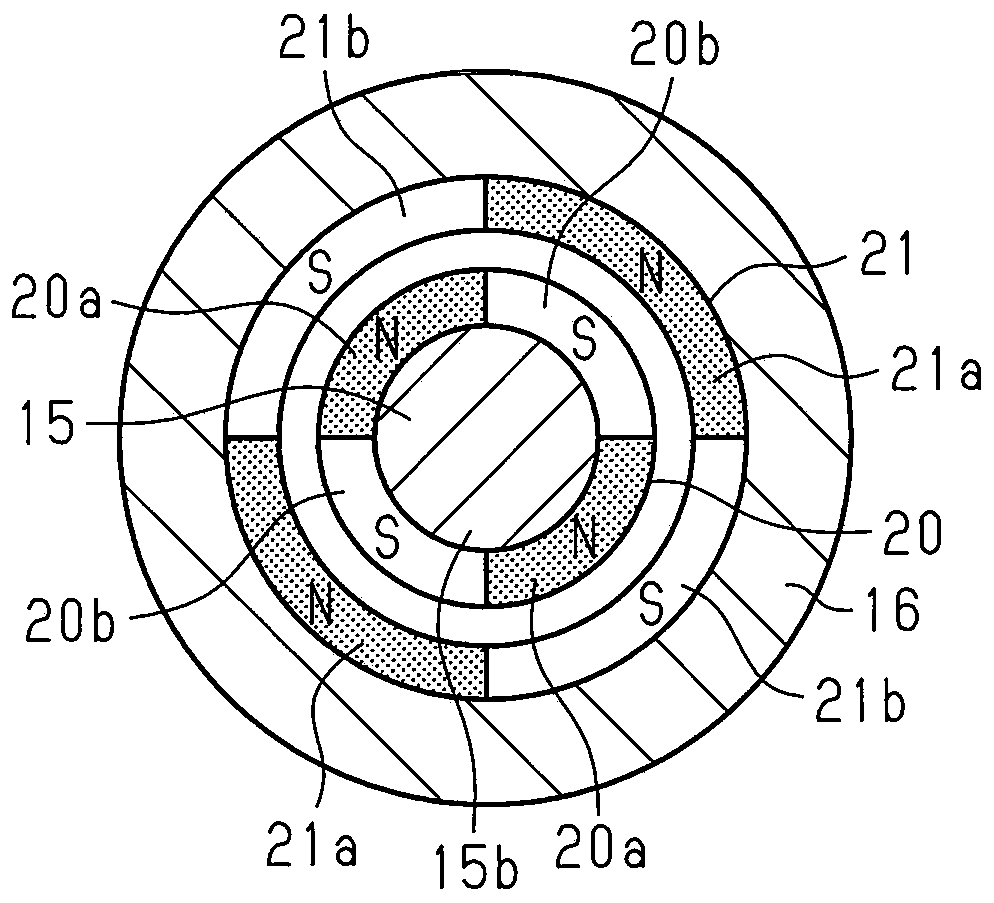
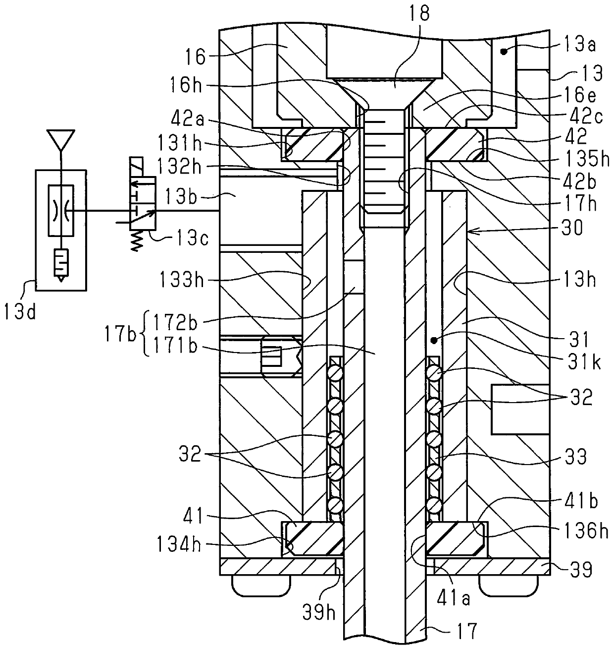
The present invention relates to a suction dampening apparatus which can be used by mounting on a front end of an XYZ actuator. An objective of the present invention is to have a convenient and inexpensive configuration, and allow high-precision rotational position determination on a loading position of an object to be transported in a long term. A driving shaft magnet (20) is installed on an outer circumferential surface of a driving shaft (15) connected to a rotary shaft (14a), and a driven shaft magnet (21) is installed on an inner circumferential surface of a driven shaft (16) connected to a movable shaft (17). And surfaces of an outer circumferential surface of the driving shaft magnet (20) and an inner circumferential surface of the driven shaft magnet (21) facing each other are magnetized to different magnetic polarities to prevent the driving shaft (15) and the driven shaft (16) from coming in contact with each other and integrally rotate in a rotational direction. While the movable shaft (17) is supported in a direction perpendicular to an axial direction of the movable shaft (17) with respect to a main body housing (13) by a bearing (30), an axial movement on the movable shaft (17) and rotation of the movable shaft (17) are allowed.

Description

technical field [0001] The present invention relates to an adsorption cushioning device for adsorbing an object to be conveyed, such as an electronic component. Background technique [0002] In general, an adsorption cushioning device that adsorbs an object to be conveyed, such as an electronic component, is attached to the actuator. The suction cushioning device has a suction unit that suctions the object to be conveyed. Then, when the object to be conveyed is sucked by the suction unit, the actuator is driven to move the suction cushioning device toward the object to be conveyed, and the suction unit is pressed against the object to be conveyed. At this time, if the pressing force applied to the object to be conveyed is too large, the object to be conveyed may be damaged. However, when the pressing force applied to the object to be conveyed is too small, there is a possibility that the object to be conveyed cannot be adsorbed by the adsorption unit. [0003] Therefore, ...

Claims


Application Information

Patent Timeline
Patent Type & Authority Patents(China)
IPC IPC(8): B65G47/91
CPCB65G47/914B65G2201/02B65G47/91B65G49/061B65G2201/022B65G2249/04
Inventor 松永晴广伊藤秀和林本茂伊藤正斋竹内亲平
Owner CKD
Learn More