
Air supplying device

A technology of air supply device and air outlet hood, which is applied to pump devices, components of pumping devices for elastic fluids, non-variable-capacity pumps, etc., can solve the problem of poor reliability against deformation, high cost, and low practicability problems, to achieve the effect of promoting indoor air circulation, increasing anti-deformation ability, and improving user experience

Pending Publication Date: 2018-06-05
ZHEJIANG CROSSBOW BRAND ELECTRIC CO LTD
View PDF7 Cites 2 Cited by
  • Summary
  • Abstract
  • Description
  • Claims
  • Application Information

AI Technical Summary

Problems solved by technology

[0003] 1) The air supply distance of the air supply device is not ideal. The main reason is that the axial length of the air outlet is relatively short, which cannot effectively extend the air supply distance. The air volume felt is already very small, seriously affecting the user experience
[0004] 2) The deformation suppressing part of the air blowing device is arranged on the windward side (that is, the inner side) of the air blowing outlet. Although it can prevent the deformation of the air blowing outlet to a certain extent, when the front end of the housing where the air blowing outlet is located is subjected to external When the pressure is high, such as extrusion when packing the box, it may still cause the air outlet to be squeezed and deformed, so the reliability of anti-deformation is poor
[0005] 3) The fan device has two air paths, one is the first air path connecting the air suction inlet and the air blowing outlet, and the other is the second air path connecting the induced air inlet and the induced air blowing outlet, but in actual use It was found that the role of the second air path was not obvious, but instead caused a large waste of space at the front of the casing, which not only affected the overall aesthetics of the fan device, but also made the structure of the fan device more complicated and the cost more expensive. high
[0006] 4) The fan device cannot rotate left and right or up and down, and cannot meet people's needs for the air supply range in the horizontal or vertical direction, and the practicability is not high

Method used


Image

  • Air supplying device
  • Air supplying device
  • Air supplying device

Examples


Embodiment Construction

[0032] The present invention will be described in further detail below in conjunction with the embodiment given with accompanying drawing.

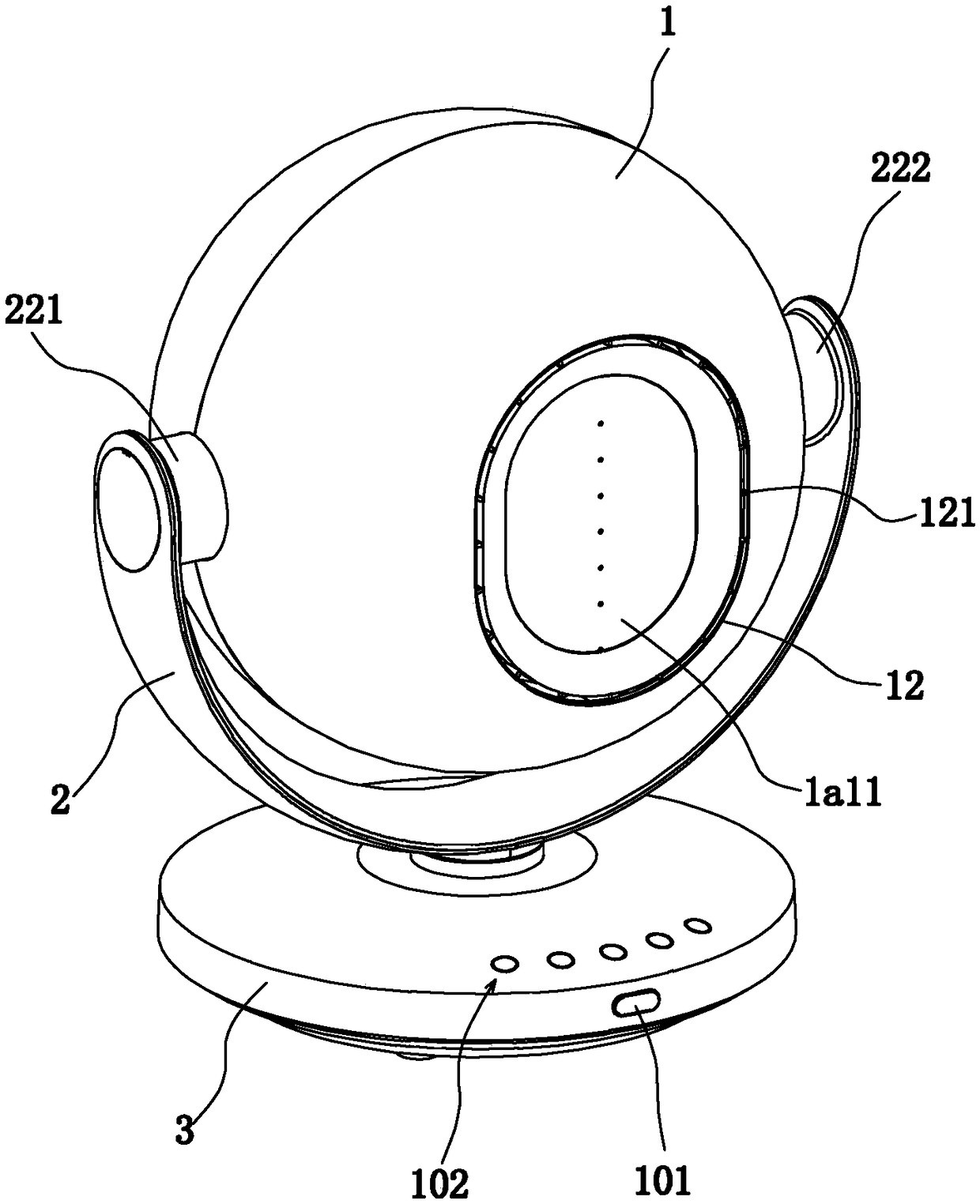
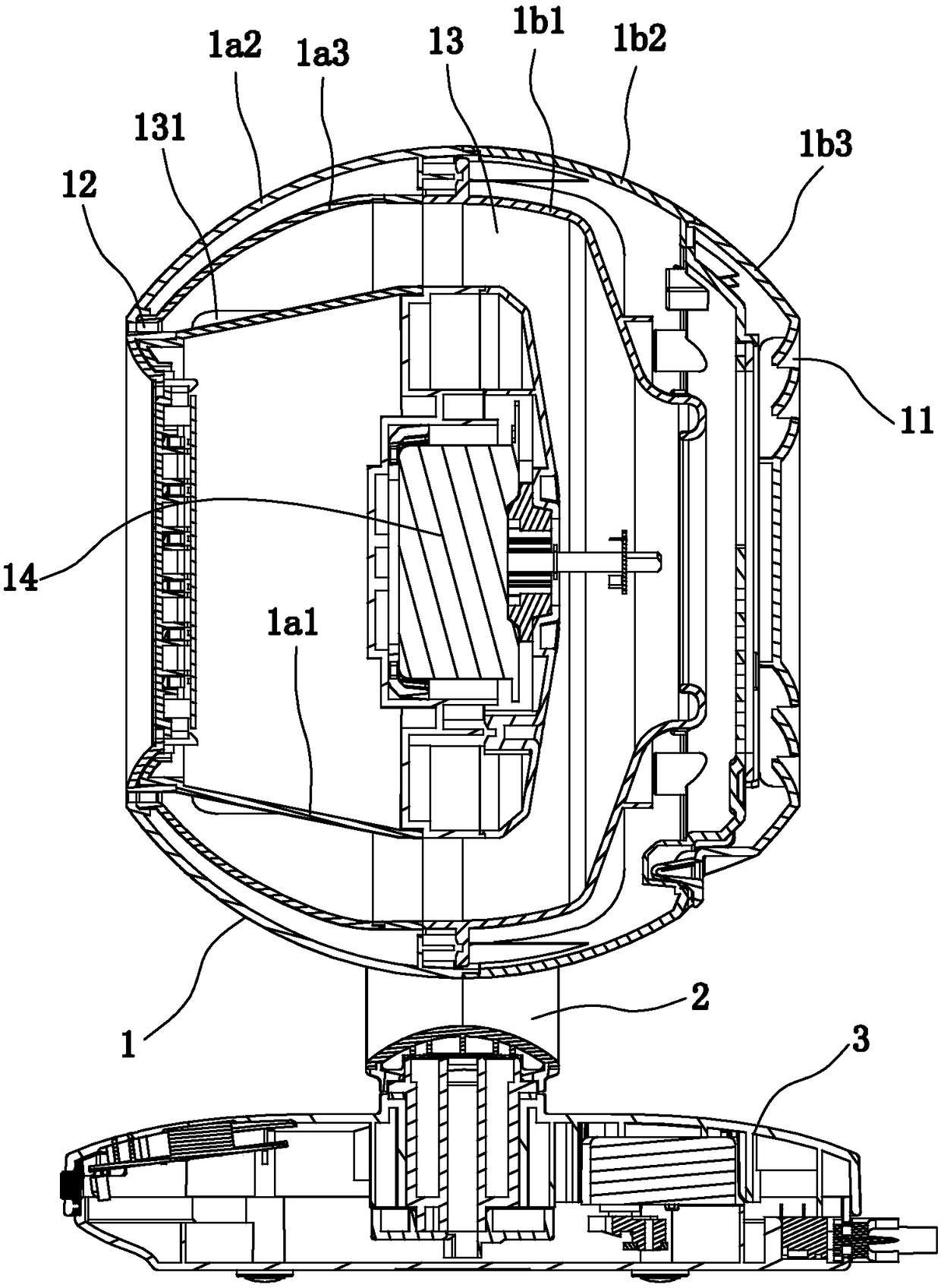
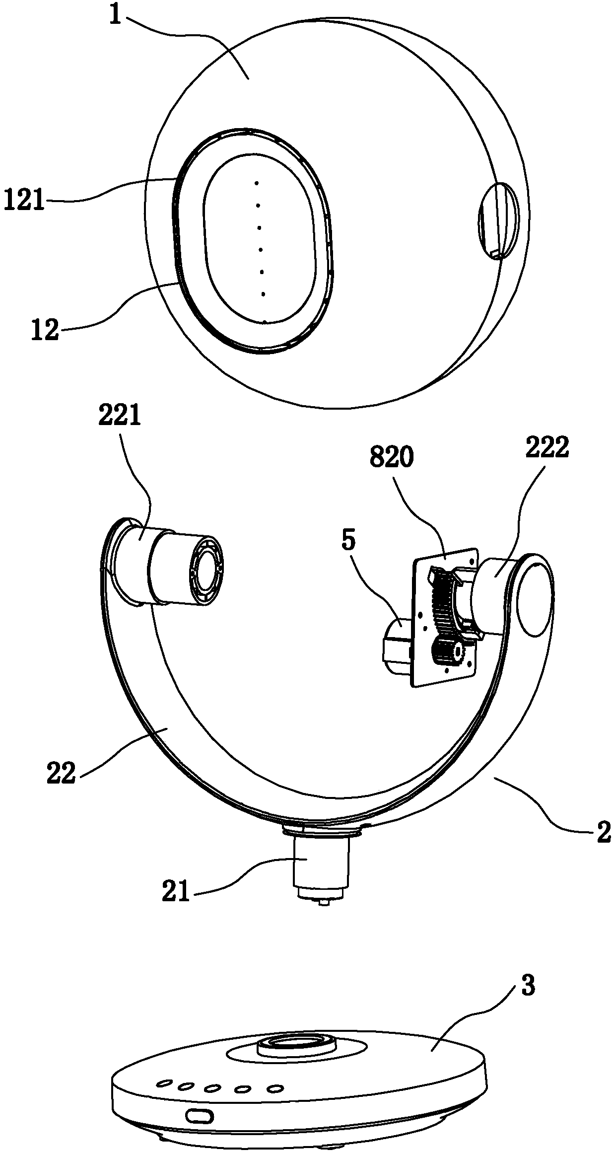
[0033] Such as Figure 1 to Figure 8 As shown, an air supply device according to the present invention includes a device main body 1, a bracket 2 and a base 3. The device main body 1 has an air suction port 11, an air blowing port 12, and is used to communicate with the air suction port 11 and the air blowing port 12. The airflow channel 13 is provided with an airflow generating device 14 in the airflow channel 13, and the air outlet 12 is in the shape of an annular slit, and the annular slit-shaped air outlet 12 extends vertically from the front end of the device main body 1 to the inside of the device main body 1. distance, and the annular slit-shaped air outlet 12 is also provided with several deformation restraints 121 connected to the two inner surfaces of the air outlet 12, and the part adjacent to the air outlet 12 in the airflow c...


PUM


Abstract

The invention relates to an air supplying device which comprises a device main body, a support and a base, wherein the device main body comprises an air sucking inlet, an air blowing outlet and an airflow channel for communicating the air sucking inlet and the air blowing outlet; an air flow generating device is arranged in the air flow channel, the air blowing outlet is in an annular narrow slit, and the air blowing outlet in the annular narrow slit shape perpendicularly extends out in a certain distance from the front end face of the device main body into the device main body; furthermore,a plurality of deformed inhibition parts which are connected with two inner lateral sides of the air blowing outlet are further arranged in the air blowing outlet in the annular narrow slit shape, anda plurality of air flow guiding parts for guiding air flow to the air blowing outlet are arranged in a part, close to the air blowing outlet in the air flow channel. The air supply device disclosed by the invention has the advantages of simple structure, far air supplying distance, high reliability, multidirectional rotation, increased wind area, convenience, practicability and the like.

Description

technical field [0001] The invention relates to an air supply device, which belongs to the technical field of household fans. Background technique [0002] Chinese invention patent ZL201680007088.7 discloses an air supply device, which includes: a main body shell with an air blowing port and an air suction port; Generating device; the air blowing outlet is slit-shaped, and there is an open air passage connected to the air blowing outlet on the windward side of the air blowing outlet, and the opening air passage of the opening air passage is perpendicular to the air blowing direction The size of the surface is larger than the size of the surface perpendicular to the air blowing direction of the air blowing port, and a deformation suppressing part that suppresses the deformation of the air blowing port is provided in the opening air passage part, and the main body case also has a round A circular opening in the shape of a cylinder, and a cylindrical cylindrical portion having...

Claims


Application Information

Patent Timeline
Patent Type & Authority Applications(China)
IPC IPC(8): F04D25/10F04D29/42F04D29/44F04D29/66F04D29/00
CPCF04D25/105F04D29/002F04D29/4226F04D29/441F04D29/668
Inventor 应辉
Owner ZHEJIANG CROSSBOW BRAND ELECTRIC CO LTD
Learn More