A system including a sea valve and its transmission device

A technology of transmission device and sea valve, which is applied in the direction of valve device, valve operation/release device, valve lift, etc. It can solve the problems of large number of fulcrums, large distance, stuck transmission device, etc., and achieve long power transmission distance and high efficiency The effect of long-distance transmission and strong coordination ability of deformation

Active Publication Date: 2019-07-12
CHINA SHIP DEV & DESIGN CENT
View PDF4 Cites 0 Cited by
  • Summary
  • Abstract
  • Description
  • Claims
  • Application Information

AI Technical Summary

Problems solved by technology

The current ballast water tank sea valve and transmission device mainly have the following problems: stuck at a large depth; the difficulty of long-distance power transmission in the horizontal direction; many friction pairs, large resistance, and low reliability
In actual use, there are the following problems: (1) At a large depth, the distance between the pressure body and the light shell changes, and the existing sea valve transmission device lacks an adaptive mechanism, and the transmission device will be stuck; (2) In the case where the ballast water tank is far away from the pressure shell and the transmission device is required for long-distance power transmission, the distance between the two fulcrums of the transmission device is relatively large, the rod is easy to lose stability, and the number of fulcrums is relatively large, and there are many friction pairs. Difficulty in distance power transmission

Method used


Image

  • A system including a sea valve and its transmission device
  • A system including a sea valve and its transmission device
  • A system including a sea valve and its transmission device

Examples


Embodiment Construction

[0025] In order to have a clearer understanding of the technical features, purposes and effects of the present invention, the specific implementation manners of the present invention will now be described in detail with reference to the accompanying drawings.

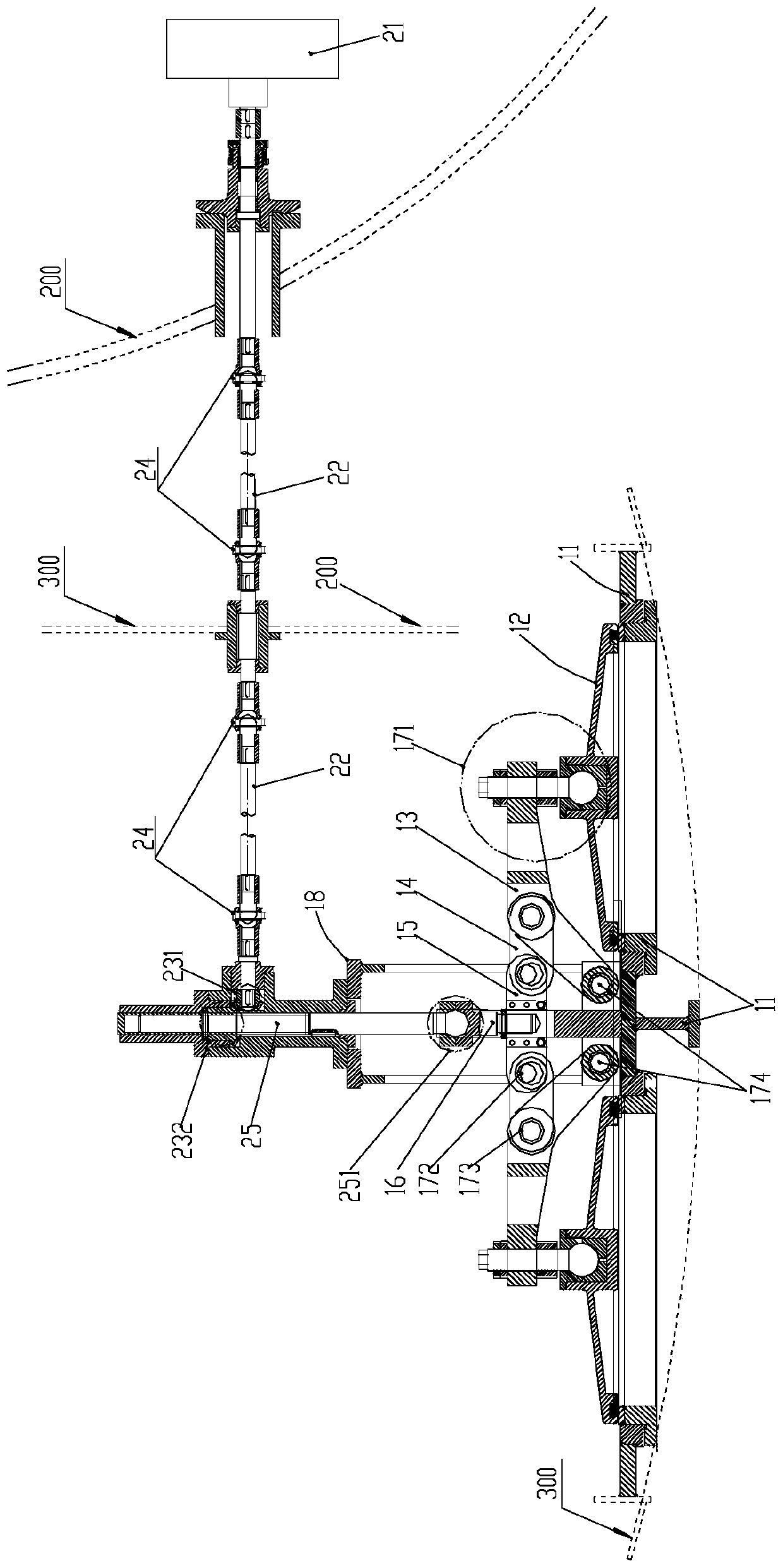
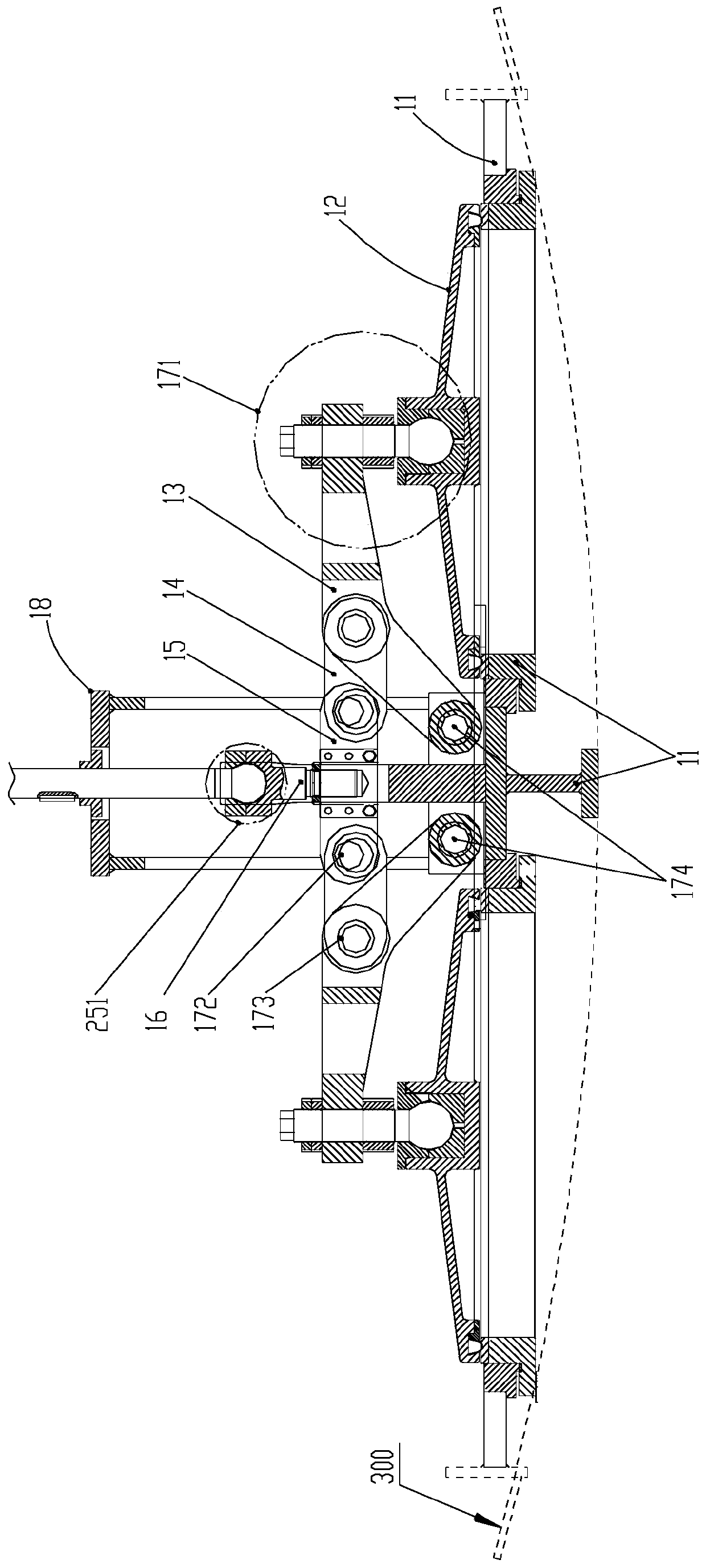
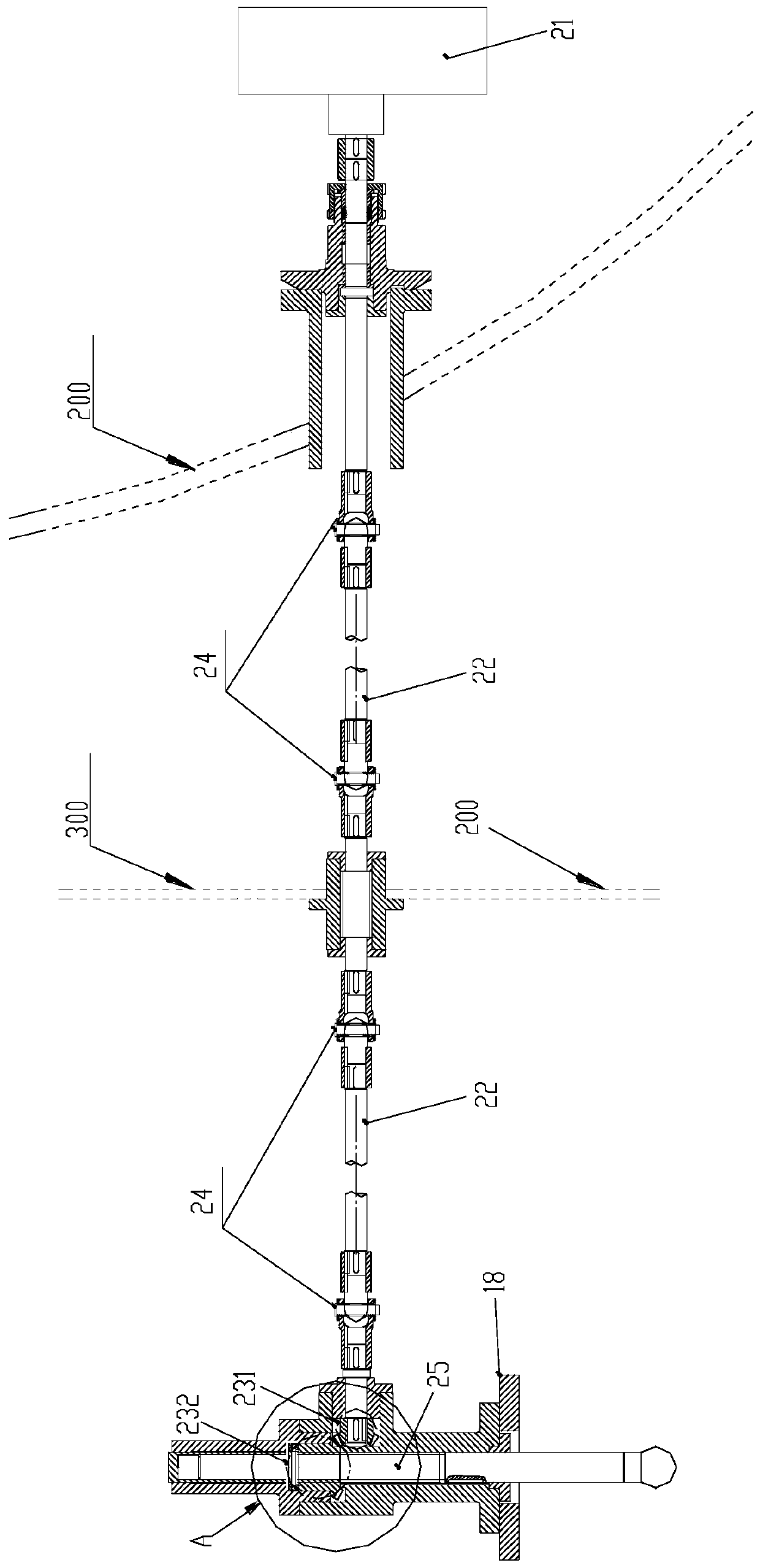
[0026] Such as figure 1 As shown, it is a system containing a sea valve and its transmission device in a preferred embodiment of the present invention, including a sea valve body 10 and a transmission device 20, and the sea valve body 10 includes a valve seat 11, a valve cover 12, and a rocker arm 13 , connecting rod 14, balance beam 15 and transmission rod 16, balance beam 15 is movably installed on valve seat 11, valve cover 12 is installed on both sides of valve seat 11, rocker arm 13 is installed on both sides of balance beam 15, rocker arm 13 is a folded arm shape, the outer end of the rocker arm 13 is connected to the valve cover 12 through the first spherical hinge 171, and the inner end is hinged to the valve se...


PUM


Abstract

The invention relates to a sea valve and a transmission device thereof. A valve body of the sea valve comprises a valve seat, valve covers, a rocker arm, a connecting rod, a balance beam and a transmission rod. The balance beam is movably mounted on the valve seat, and the valve covers are mounted on the two sides of the balance beam. The outer end of the rocker arm is connected to the valve coverthrough a first ball joint, the inner end of the rocker arm is hinged to the valve seat, and the rocker arm is hinged to the balance beam through the connecting rod. The balance beam, the connectingrod and the rocker arm form a rocker arm link mechanism, and the transmission rod is fixedly connected to the balance beam; and a transmission device comprises a transmission mechanism, a transmissionshaft, a bevel gear, a bevel gear nut and a ball head screw. One end of the transmission shaft is connected with the transmission mechanism, the other end is connected with the bevel gear, and the bevel gear nut is meshed with the bevel gear, the ball head screw and the bevel gear nut are connected to form a lead screw pair, and the ball head screw is connected with the transmission rod of the valve body of the sea valve through a second ball joint. According to the sea valve, power-efficient and long-distance transmission can be achieved, the transmission mechanism is of a rotating shaft type structure, a main transmission member only bears the torsional load effect, and the problem of rod piece instability occurring in a push rod type structure does not occur.

Description

technical field [0001] The invention relates to the technical field of ship equipment, in particular to a system including a sea valve and a transmission device installed in a ballast water tank. Background technique [0002] The sea valve is mainly installed at the bottom of the ballast water tank of the hull, and is opened when the ballast water tank is filled with water and drained, and serves as a passage for seawater in and out of the ballast water tank. The ballast tank sea valve and its transmission device are important components of the submersible system. The sea valve and its transmission device need to open and close the ballast water tank inlet and outlet smoothly and without stagnation within the specified time. The current ballast water tank sea valves and transmission devices mainly have the following problems: stagnation at large depths; long-distance power transmission in the horizontal direction is difficult; there are many friction pairs, large resistance,...

Claims


Application Information

Patent Timeline
Patent Type & Authority Patents(China)
IPC IPC(8): F16K1/00F16K1/32F16K31/46F16K31/50F16K31/53
CPCF16K1/00F16K1/32F16K31/46F16K31/50F16K31/53
Inventor 陈志文张军军孙龙飞李志印许建
Owner CHINA SHIP DEV & DESIGN CENT
Why Eureka
Try Eureka