New energy electric vehicle charging system
A technology of electric vehicles and charging systems, applied in the direction of electric vehicle charging technology, electric vehicles, charging stations, etc., can solve the problems of high power consumption, traffic congestion, and long time spent on half-way parking and charging, etc.
- Summary
- Abstract
- Description
- Claims
- Application Information
AI Technical Summary
Problems solved by technology
Method used
Image
Examples
Embodiment 1
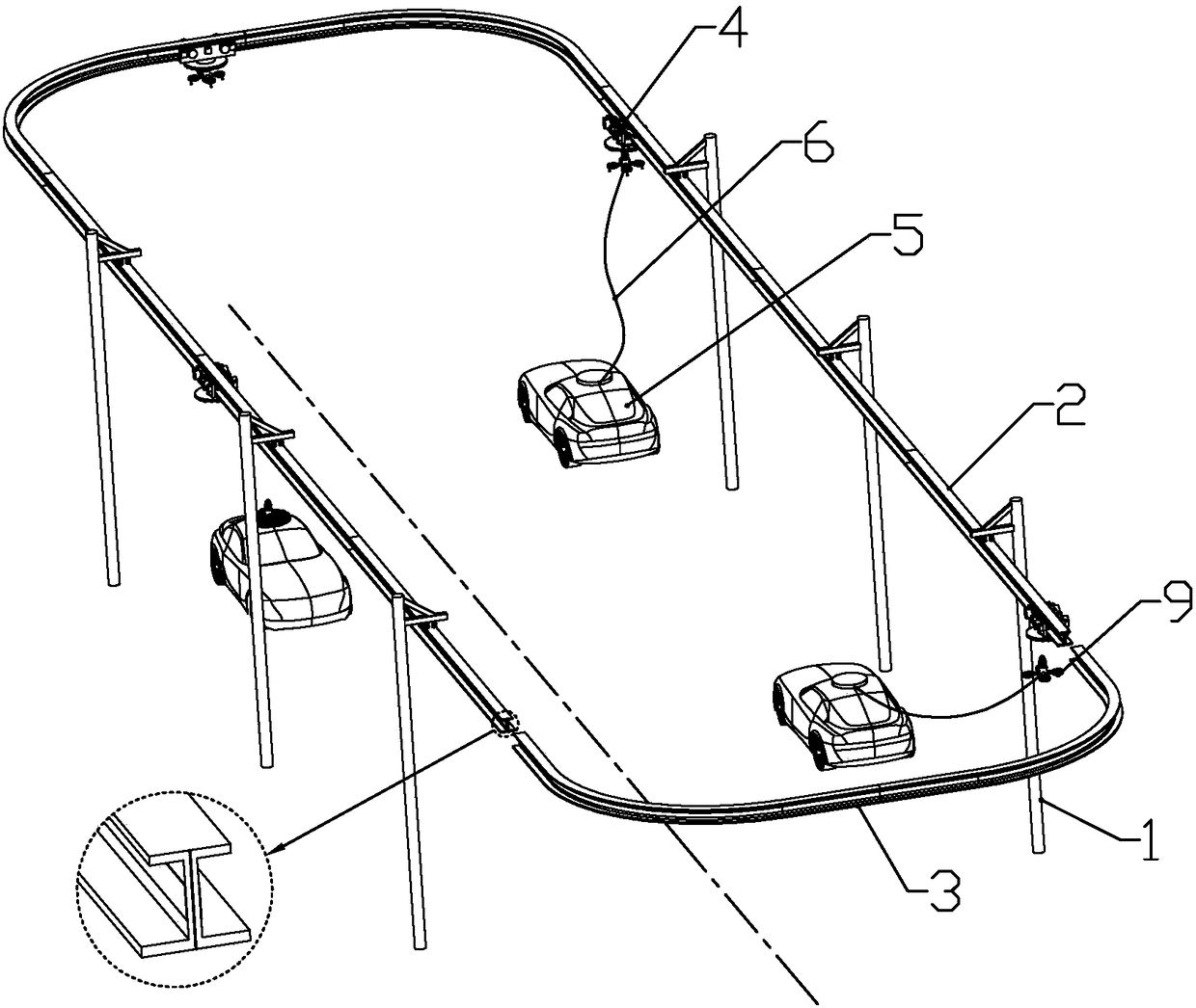
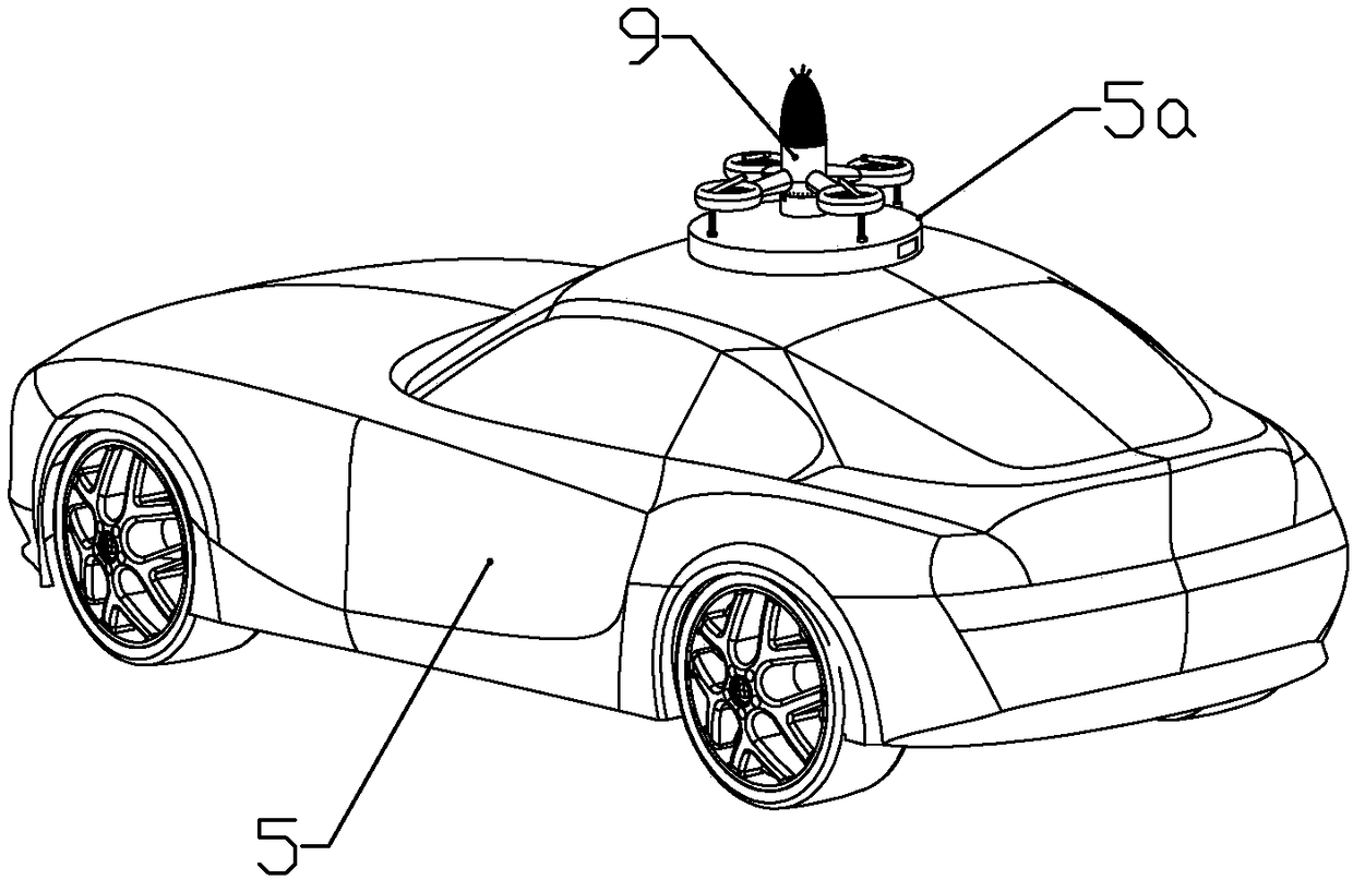
[0085] according to Figures 1 to 6 As shown, this embodiment is a new energy electric vehicle charging system, including a plurality of power transmission poles 1 fixedly installed on both sides of the road, power transmission guide rails 2 installed between the power transmission poles on the same side of the road, rolling or sliding The guide rail car 4 that is installed on the described power transmission guide rail and is electrically connected with the power transmission guide rail, the aircraft 9 that can be parked at the lower end of the guide rail car and is electrically connected with the guide rail car, and is connected between the electric vehicle and the aircraft in order to transfer electric energy from the power transmission The guide rail is transmitted to the wire 6 on the electric vehicle.
[0086] The wire refers to the whole wire, and the wire includes 2 wires.
[0087] The power transmission guide rail is spliced by two symmetrical U-shaped steel rails ...
Embodiment 2
[0112] combine Figure 7 to Figure 15 As shown, this embodiment makes the following improvements on the basis of Embodiment 1: the aircraft includes a main body 91, and the main body includes a circular tube-shaped fan mounting portion 910, which is connected to the outer periphery of the fan mounting portion and connected to the fan Four equidistantly arranged connecting pipes communicated with the installation part, and an air outlet ring 911 connected to the outer end of each connecting pipe and communicated with the corresponding connecting pipe.
[0113] The upper bracket 9101 is connected to the fan installation part above the connecting pipe, and the upper driving fan 951 is installed on the upper bracket; the lower bracket 9102 is connected to the fan installation part below the connecting pipe, and the lower bracket is installed There is a lower driving fan 952; the turning direction of the upper driving fan is opposite to that of the lower driving fan, and the inner ...
Embodiment 3
[0131] combine Figure 16 to Figure 17 In this embodiment, the following improvements are made on the basis of Embodiment 2: a landing gear joint 9110 is formed on the inner circumference of each of the air outlet rings away from the connecting pipe, and a landing gear 93 is connected to each of the landing gear joints The landing gear includes a connecting pipe body 931 that is fixedly connected with the landing gear joint and communicates with the inside of the air outlet ring through the landing gear joint, and the sliding pipe 932 that is slidably installed in the connecting pipe body is close to the landing gear joint with the connecting pipe body One end of the support rod 935 is rotatably connected, the second electromagnet 936 connected to the end of the support rod away from the landing gear joint is used to attract and tighten the top of the electric vehicle, and the connecting rod 934 is respectively rotatably connected to the middle part of the sliding tube and the ...
PUM
 Abstract
Description
Claims
Application Information
 - R&D
- Intellectual Property
- Life Sciences
- Materials
- Tech Scout
- Unparalleled Data Quality
- Higher Quality Content
- 60% Fewer Hallucinations
Browse by: Latest US Patents, China's latest patents, Technical Efficacy Thesaurus, Application Domain, Technology Topic, Popular Technical Reports.
© 2025 PatSnap. All rights reserved.Legal|Privacy policy|Modern Slavery Act Transparency Statement|Sitemap|About US| Contact US: help@patsnap.com


