Heat dissipation water tank structure of water cooling system

A technology of cooling water tank and water cooling system, which is applied to household refrigeration devices, lighting and heating equipment, cooling fluid circulation devices, etc. The effect of increasing convenience and practicality

Active Publication Date: 2018-06-08
KUAN DING TECH
View PDF6 Cites 2 Cited by
  • Summary
  • Abstract
  • Description
  • Claims
  • Application Information

AI Technical Summary

Problems solved by technology

However, if the water volume inside the water tank does not reach a certain height, the connected water pump may cause blockage due to the air sucked into the water tank, and the water pump may also be damaged due to idling
In add

Method used


Image

  • Heat dissipation water tank structure of water cooling system
  • Heat dissipation water tank structure of water cooling system
  • Heat dissipation water tank structure of water cooling system

Examples


Embodiment Construction

[0073] The detailed description and technical content of the present invention are described below with the accompanying drawings, but the attached drawings are only for reference and illustration, and are not intended to limit the present invention.

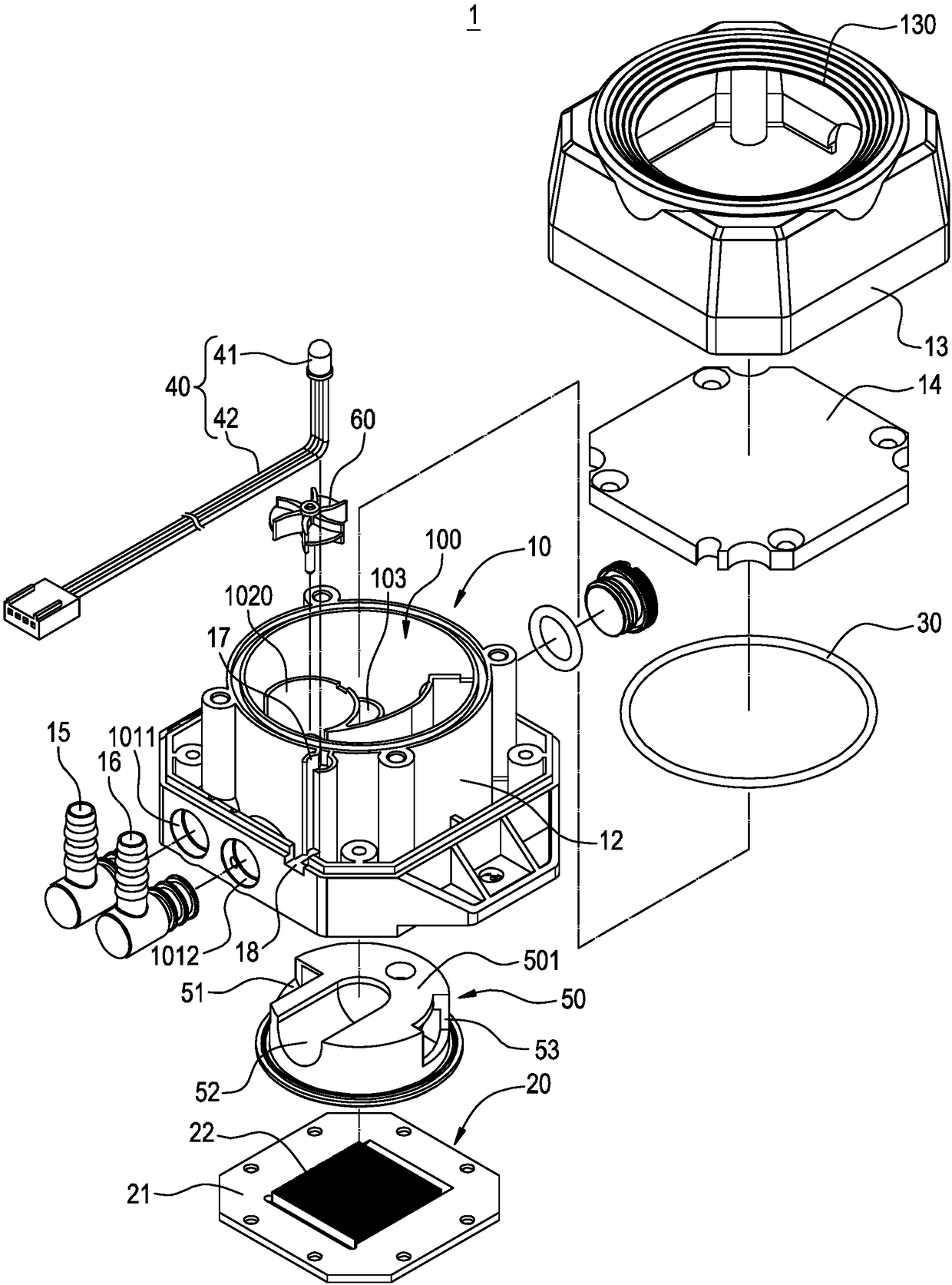
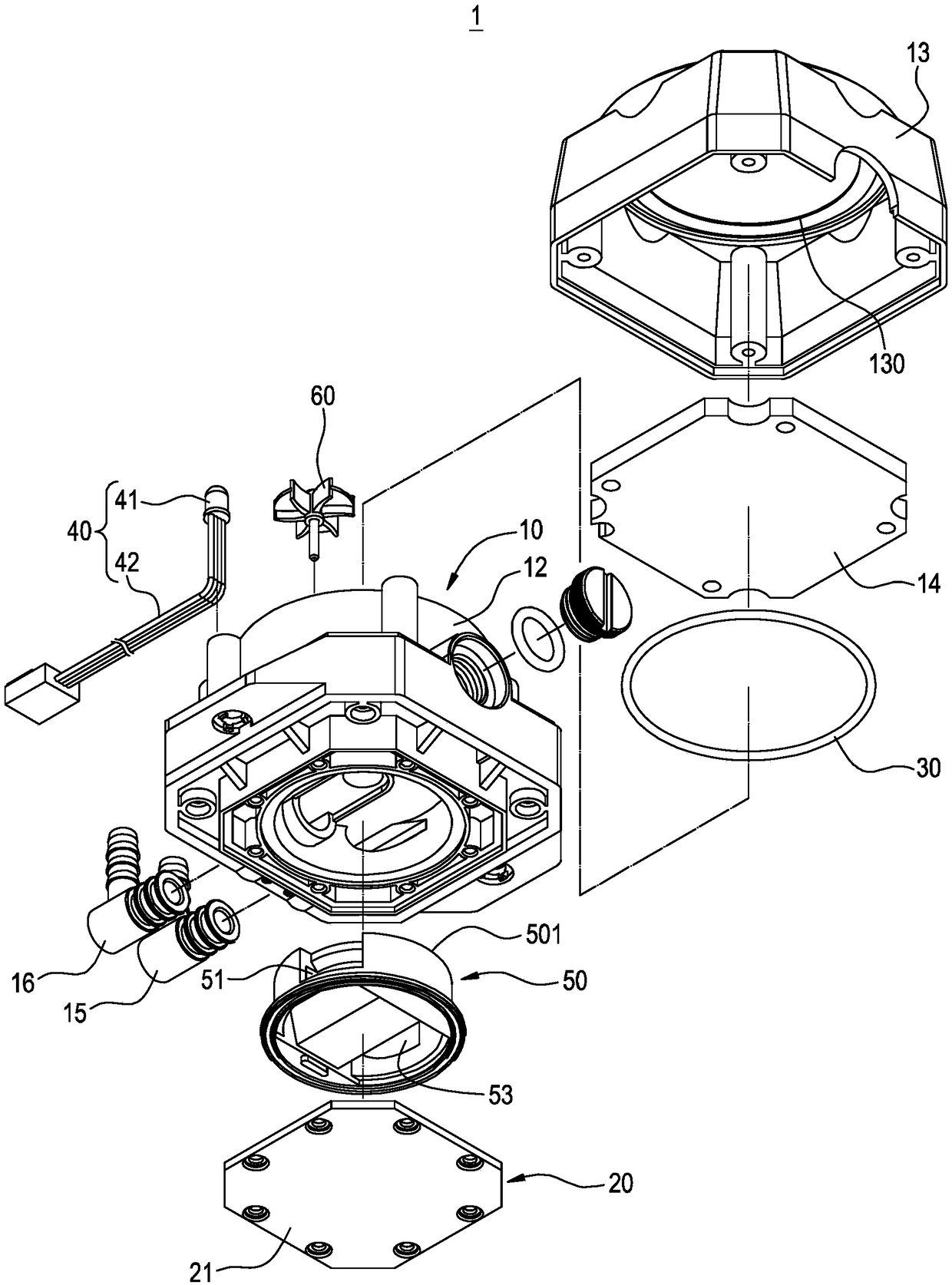
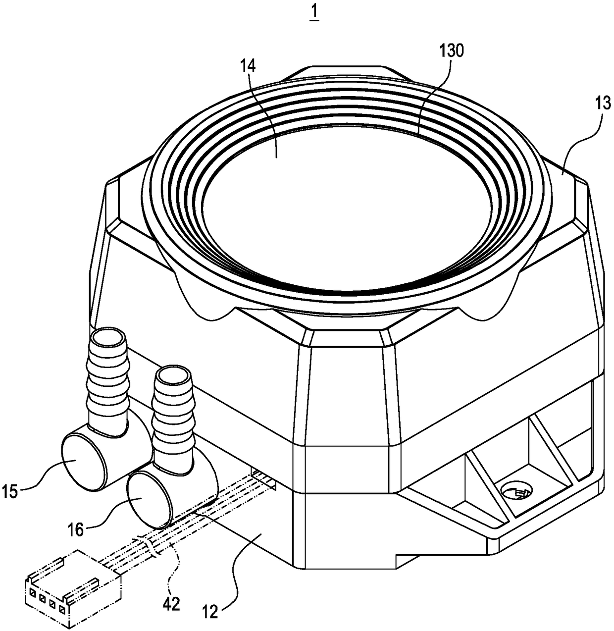
[0074] see Figure 1 to Figure 5 , which respectively show the three-dimensional exploded schematic diagram, the three-dimensional appearance schematic diagram, the three-dimensional appearance schematic diagram of the water distribution seat, and the one-side (longitudinal) cross-sectional view of the cooling water tank structure of the water cooling system of the present invention. The present invention provides a heat dissipation water tank structure 1 of a water cooling system, which includes a shell base 10 and a water cooling plate group 20 . The water-cooled plate assembly 20 is combined with an outer surface of the shell base 10 for adhering to a heat source and dissipating heat therefrom. The structure of the radiator ...


PUM


Abstract

The invention relates to a heat dissipation water tank structure of a water cooling system, and the structure comprises a shell seat and a water cooling plate set. The shell seat has a water inlet, awater outlet and a partition for the accommodating space to connect the accommodating space, and the partition accommodating space is a heat exchange area and a water collecting area, and the shell seat has a conveying pipe which is communicated with the heat exchange zone and the nozzle of the conveying pipe is located in the water collecting area. The water-cooling plate group is combined with the shell seat and covers one side of the heat exchange area, wherein the heat-dissipating water tank structure can cover the nozzle of the conveying pipe through the cooling liquid in the water collecting area. It is arranged at any angle or direction. Accordingly, the air does not enter the water pump connected to the radiator tank structure, and the operation can be maintained, and the convenience in setting is increased.

Description

technical field [0001] The invention relates to a water cooling system, in particular to a water tank structure of the water cooling system. Background technique [0002] Generally speaking, when water (liquid) cooling is used for heat dissipation, the water cooling system generally includes components such as a water tank, a water cooling head attached to a heating element, a water pump (pump) connected to the water tank, a water cooling row, and connecting pipelines. When the system is in use, the water cooling head is pasted on the surface of a heating element for heat exchange, thereby achieving the purpose of cooling the heating element. [0003] When using a traditional water-cooled heat sink, the water tank may have to be set at different angles and directions due to the different positions of the heating elements, such as vertical (0 degrees), horizontal (90 degrees) or reverse (180 degrees), etc. However, if the water volume inside the water tank does not reach a c...

Claims


Application Information

Patent Timeline
IPC IPC(8): F25D1/02F25D17/02
CPCF25D1/02F25D17/02
Inventor 潘冠达
Owner KUAN DING TECH
Why Eureka
Try Eureka