
Display panel and display device

A technology for display panels and substrates, applied in instruments, nonlinear optics, optics, etc., can solve problems such as affecting display effect, affecting image quality, light leakage, etc., to avoid reflection and dark state light leakage, uniformity in all parts, and avoid black areas Effect

Active Publication Date: 2020-05-22
XIAMEN TIANMA MICRO ELECTRONICS
View PDF15 Cites 0 Cited by
  • Summary
  • Abstract
  • Description
  • Claims
  • Application Information

AI Technical Summary

Problems solved by technology

However, in the currently used display panel bending mode, since the upper substrate and the lower substrate of the display panel have different arcs corresponding to the same length after bending, the alignment deviation increases from the center of the screen to both sides along the bending direction, and the central aperture ratio is greater than that of the two sides. Aperture ratio, the brightness at both ends is darker than the curved center of the screen, which affects the display effect
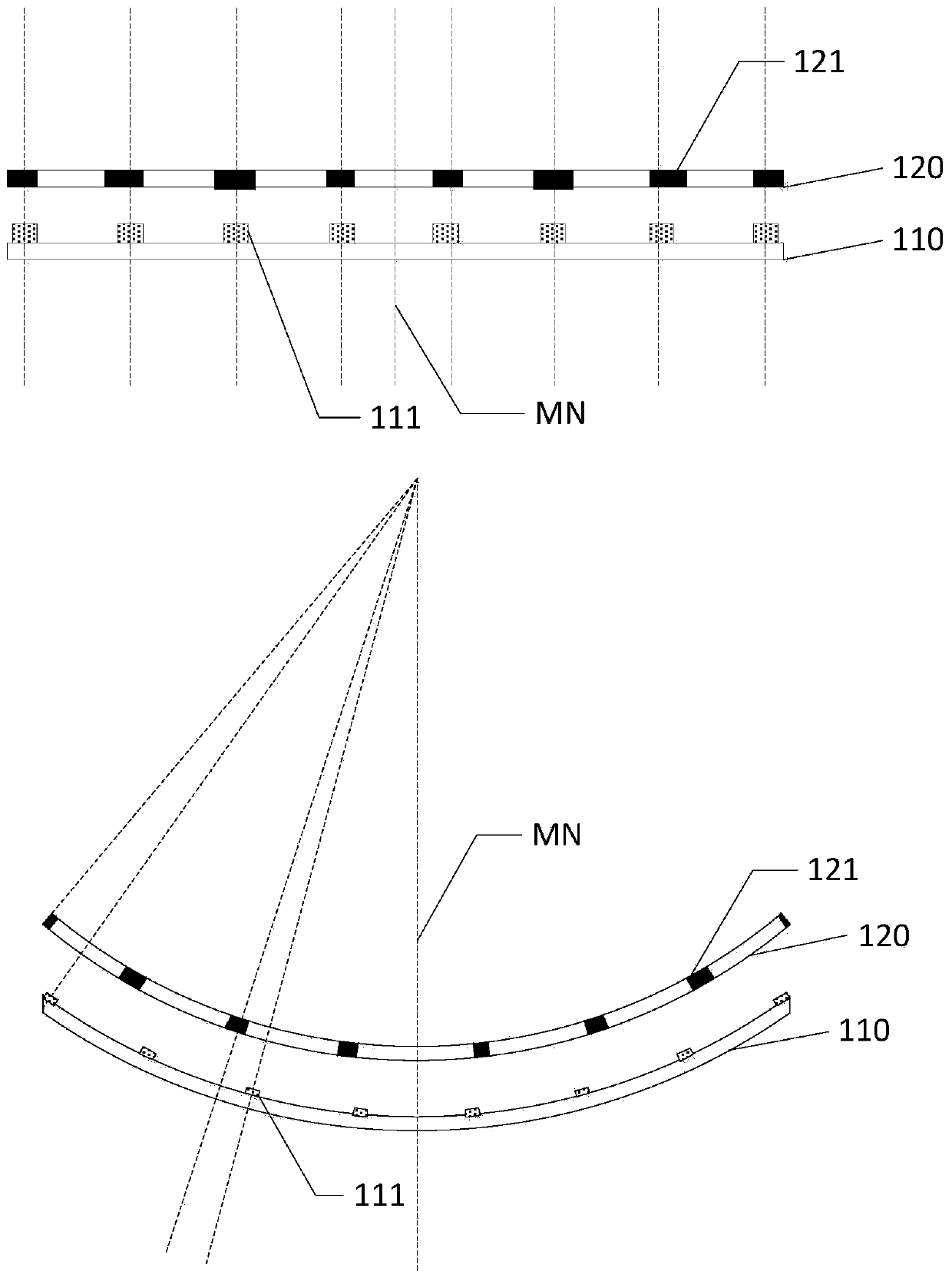
[0003] Furthermore, if figure 1 as shown, figure 1 It is a schematic diagram of the structure comparison of the display panel in the prior art before and after bending. When the screen is bent, the black matrix (Black Matrix, BM for short) 121 on the second substrate 120 on both sides and the first substrate The alignment deviation of the metal lines 111 on the 110 increases, and the black matrix 121 cannot cover the metal lines 111 on the first substrate side, resulting in light reflection and light leakage in dark states, a decrease in contrast, and a serious impact on image quality

Method used


Image

  • Display panel and display device
  • Display panel and display device
  • Display panel and display device

Examples


Embodiment Construction

[0030] The following will clearly and completely describe the technical solutions in the embodiments of the present invention with reference to the accompanying drawings in the embodiments of the present invention. Obviously, the described embodiments are only some, not all, embodiments of the present invention. Based on the embodiments of the present invention, all other embodiments obtained by persons of ordinary skill in the art without creative efforts fall within the protection scope of the present invention.

[0031] Terms used in the embodiments of the present invention are only for the purpose of describing specific embodiments, and are not intended to limit the present invention. As used in the embodiments of the present invention and the appended claims, the singular forms "a", "said" and "the" are also intended to include the plural forms unless the context clearly indicates otherwise.

[0032] It should be understood that the term "and / or" used herein is only an as...


PUM


Abstract

The invention discloses a display panel and a display device. The display panel is bent to form a curved surface display panel; a plurality of sub-pixel regions are arranged on a second substrate of the display panel in an array; each sub-pixel region comprises a sub-pixel opening region; black matrixes are arranged at other regions, except the sub-pixel regions, on the second substrate. The second substrate is bent by taking an axis as the center and an axis direction is a third direction and; a direction vertical to the axis direction is a fourth direction; a black matrix between the adjacent sub-pixel openings in the fourth direction is a first black matrix; the width of the first black matrix in the fourth direction is gradually increased from the axis to two sides of the axis of the second substrate; a black matrix between the adjacent sub-pixel openings in the third direction is a second black matrix; the width of the second black matrix in the third direction is gradually reduced from the axis to two sides of the axis of the second substrate. By adopting the display panel and the display device with the structure, light reflection, dark-state light leakage and edge dark masscan be avoided.

Description

technical field [0001] The invention relates to the field of display technology, in particular to a curved display panel and a display device formed by bending a flat display panel. Background technique [0002] With the rapid development of display technology, the market's requirements for display products are gradually increasing. Curved surface displays are attracting more and more attention due to their beautiful appearance, realistic picture sense and comfortable human eye experience. However, in the current bending mode of the display panel, since the upper substrate and the lower substrate of the display panel have different arcs corresponding to the same length after bending, the alignment deviation increases from the center of the screen to both sides along the bending direction, and the central opening ratio is larger than that of the two sides. Aperture ratio, the brightness at both ends is darker than the curved center of the screen, which affects the display eff...

Claims


Application Information

Patent Timeline
Patent Type & Authority Patents(China)
IPC IPC(8): G02F1/1335G02F1/1333
CPCG02F1/1333G02F1/133512
Inventor 马扬昭陈宝玲吴玲沈柏平
Owner XIAMEN TIANMA MICRO ELECTRONICS
Learn More