Top-mounted multifunctional camera cart and special slide rails for studio

A camera car, top-mounted technology, applied in the direction of TV, machine/stand, color TV components, etc., can solve the problems of affecting audience viewing, shaking the dead angle of shooting, and affecting the quality of shooting, and achieves high accuracy and flexibility. The effect of improving sex and improving safety

Active Publication Date: 2020-07-14
ZHEJIANG OCEAN UNIV
View PDF5 Cites 0 Cited by
  • Summary
  • Abstract
  • Description
  • Claims
  • Application Information

AI Technical Summary

Problems solved by technology

[0002] In the current life, some of the TV programs you see are recorded in the studio and then broadcast. In order to ensure the effect of recording, it is necessary to build a long ladder at the position of the auditorium, and then place a camera on the upper part of the long ladder for video recording. , but this method will affect the viewing of the audience, and when the camera is controlled to switch the camera angle, there will be shaking or a shooting dead angle. The quality of the

Method used


Image

  • Top-mounted multifunctional camera cart and special slide rails for studio
  • Top-mounted multifunctional camera cart and special slide rails for studio
  • Top-mounted multifunctional camera cart and special slide rails for studio

Examples


Embodiment 1

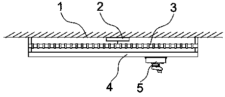
[0031] Such as figure 1 , 2 、 As shown in 3, the studio uses a roof-mounted multifunctional camera cart, including:

[0032] A movable camera trolley 5 is placed under the roof surface 1 of the chamber;

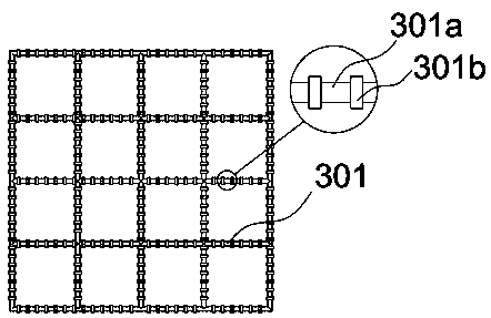
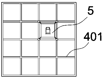
[0033] Below the roof surface 1 of the chamber, the electromagnetic layer 3 and the slide rail layer 4 are connected horizontally through connecting rods from top to bottom;

[0034] A wireless receiving controller 2 for controlling the electromagnetic layer 3 is provided on the surface of the roof 1;

[0035] The bottom of the slide track layer 4 is movably connected to the camera car 5, and the camera car 5 is placed on the top of the studio by placing the camera car 5 on the top surface 1 of the studio, and the electromagnetic layer 3 is used to drive the camera car 5, and the camera car 5 is placed above the studio. The bottom surface frees up more space for other operations, which is conducive to the progress of the studio, and it is placed above the studio to make th...

Embodiment 2

[0039] Such as Figure 4 As shown, the present embodiment is further optimized on the basis of Embodiment 1 as follows: the camera car 5 includes a frame 507, a motor 504 is arranged in the middle of the frame 507, the rotating shaft of the motor 504 is connected to a disk body, and a support block 503 and a support block 503 are arranged in the disk body. Electronically controlled telescopic rod 505, the top of the support block 503 is provided with a clip 502 that is movably connected to the camera 501, the electronically controlled telescopic rod 505 is connected to the end of the clip 502, the surface of the frame 507 is connected with a second wireless receiving controller 506, the frame The four corners of the bottom surface of 507 are connected with spherical pulleys 509 through cardan shafts 510, and are fixedly connected with the camera 501 through clips 502 to ensure the safety of the camera 501 above the studio, and control the electronically controlled telescopic ro...

Embodiment 3

[0045] Such as Figure 5-7 As shown, the present embodiment is further optimized on the basis of embodiment 1 as:

[0046] The electronically controlled telescopic rod 505 is connected to the end of the bar 502 through the buffer 6. The buffer 6 is composed of a housing 601, a buffer frame 602 and a support shaft 603. The support shaft 603 is provided with three coaxial cylindrical housings 601. The inner wall of 601 is connected with the support shaft 603 through the diamond-shaped buffer frame 602. The buffer frame 602 is made of rubber, and the surface is provided with a preferred φ0.15mm air hole. The casing 601 is connected with the electric control telescopic rod 505. If the frame 507 shakes, the buffer 6 will be shaped by the buffer frame 602 made of rubber, and the rhombus shape will be stretched or compressed to deform and greatly reduce the sense of shaking, avoiding the camera 501. Shaking is generated to ensure that the picture of the camera 501 is stable when sho...


PUM


Abstract

The invention provides a top-mounted multifunctional photographic vehicle and specially made slide rails for a studio and belongs to the technical field of a photographic device. The top-mounted multifunctional photographic vehicle for the studio comprises the fact that a movable photographic vehicle is set below a studio top surface; an electromagnetic layer and a slide rail layer which are horizontally set are connected below the studio top surface in sequence from top to bottom through a connection rod; and a wireless receiving controller for controlling the electromagnetic layer is set onthe surface of the studio top surface. According to the photographic device provided by the invention, the position movement flexibility is high, the movement is stable and precise, a photographic range is wide, influences of light and dust are avoided, and the quality of photographic images is high.

Description

technical field [0001] The invention belongs to the technical field of photographic devices, in particular to a top-mounted multifunctional camera cart and a special slide rail for a studio. Background technique [0002] In the current life, some of the TV programs you see are recorded in the studio and then broadcast. In order to ensure the effect of recording, it is necessary to build a long ladder at the position of the auditorium, and then place a camera on the upper part of the long ladder for video recording. , but this method will affect the viewing of the audience, and when the camera is controlled to switch the camera angle, there will be shaking or a shooting dead angle. The quality is often affected. Contents of the invention [0003] One of the objectives of the present invention is to provide a studio-mounted multifunctional camera cart with high flexibility in position movement, stable and precise movement, wide shooting range, no influence of light and dust...

Claims


Application Information

Patent Timeline
Patent Type & Authority Patents(China)
IPC IPC(8): H04N5/222F16M11/42
CPCF16M11/42H04N5/222
Inventor 任文轩侯长帅
Owner ZHEJIANG OCEAN UNIV
Why Eureka
Try Eureka