Dial structure, smart watch, and control method for smart watch

A dial and watch case technology, applied in the field of smart wearable devices, can solve problems such as limited shooting angle, low user experience, and troublesome operation, and achieve the effects of convenient operation, wide shooting range, and improved user experience

Pending Publication Date: 2018-11-30
GUANGDONG XIAOTIANCAI TECH CO LTD
View PDF0 Cites 0 Cited by
  • Summary
  • Abstract
  • Description
  • Claims
  • Application Information

AI Technical Summary

Problems solved by technology

[0004] However, when the user needs to use the camera to achieve different functions (such as self-portrait, scanning code, shooting the surrounding environment or video calling), since the shooting direction of the camera is fixed and the shootin

Method used


Image

  • Dial structure, smart watch, and control method for smart watch
  • Dial structure, smart watch, and control method for smart watch
  • Dial structure, smart watch, and control method for smart watch

Examples


Example Embodiment

[0112] Embodiment one

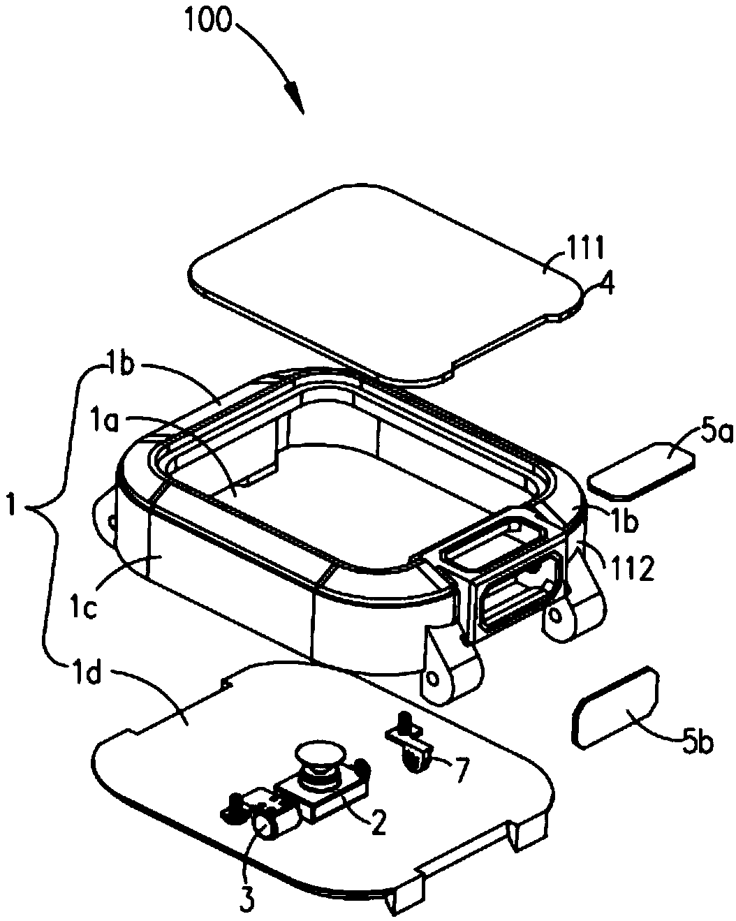
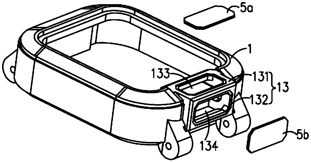
[0113] see figure 1 , Embodiment 1 of the present invention discloses a dial structure 100 , including a watch case 1 , a photographing device 2 and a driving mechanism 3 . An accommodating cavity 1a is formed inside the watch case 1, and a main board (not shown) is arranged in the accommodating cavity 1a. The photographing device 2 is arranged at one end 1b of the watch case 1 and is electrically connected with the main board, and the photographing device 2 has a first photographing posture (such as Figure 5 ) and the second shooting pose (as shown in Image 6 shown). The driving mechanism 3 is arranged at one end 1b of the watch case 1 and is electrically connected to the main board. The driving mechanism 3 is fixedly connected to the photographing device 2 and is electrically connected to the main board. The main board is used to control the driving mechanism 3 to drive the shooting device 2 to switch between the first shooting posture and the s...

Example Embodiment

[0152] Embodiment two

[0153] see Figure 10 Embodiment 2 of the present invention discloses a smart watch 200. The smart watch 200 includes a strap (not shown) and a dial structure 100 as in the first embodiment above. The dial structure 100 is connected to the strap.

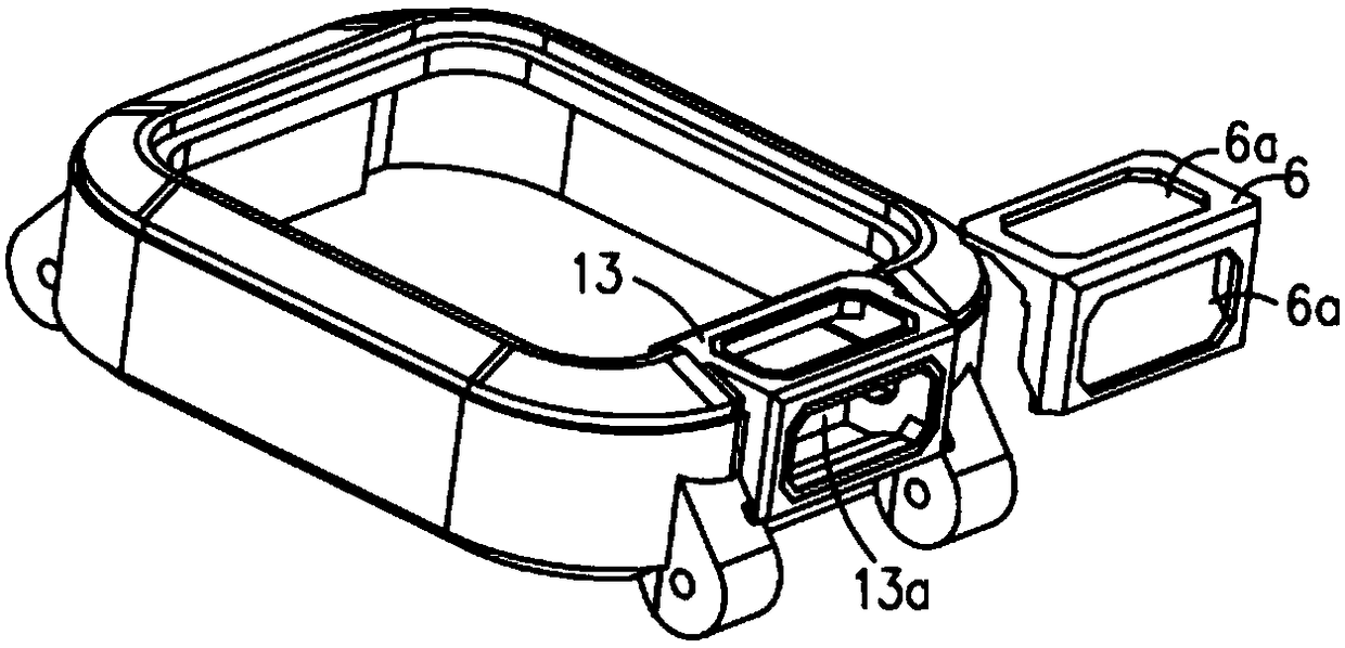
[0154] In this embodiment, the two ends of the watch case 1 of the dial structure 100 are separately provided with a strap connecting portion 101, and the strap connecting portion 101 is set near the bottom of the watch case 1, and the strap is connected to the strap connecting portion 101. Section 101. Specifically, one of the watch strap connecting parts 101 is located below the bracket 13 of the watch case 1 to avoid blocking the bracket 13 and thus avoid affecting the shooting of the camera 2 . At the same time, by arranging one of the strap connecting parts 101 under the bracket 13 of the watch case 1, the bracket 13 can also be used to cover one of the strap connecting parts 101, so that the overall a...

Example Embodiment

[0158] Embodiment Three

[0159] Embodiment 3 of the present invention discloses a control method for a smart watch. The smart watch can be the smart watch of the above-mentioned embodiment 2, and the smart watch includes the dial structure of the above-mentioned embodiment 1. Specifically, the method includes:


PUM


Abstract

The invention discloses a dial structure, a smart watch, and a control method for the smart watch. The dial structure comprises a watchcase, a shooting device and a driving mechanism. A main board isarranged in the watchcase, and the shooting device is arranged at one end of the watchcase and has a first shooting posture and a second shooting posture. A certain angle is formed between the first shooting direction of the first shooting posture and the second shooting direction of the second shooting posture. The driving mechanism is arranged at one end of the watchcase, electrically connectedwith the main board and fixedly connected with the shooting device. The main board is used for controlling the driving mechanism to drive the shooting device to switch between the first shooting posture and the second shooting posture so as to enable the shooting device to obtain different shooting angles. According to the dial structure, the smart watch, and the control method for the smart watch, the shooting angle of the shooting device can be automatically adjusted, when wanting to obtain the different shooting angles, a user does not need to manually adjust the position of the watch or take off the watch to manually adjust, the operating mode is simple, and the usage experience of the user is high.

Description

technical field [0001] The invention relates to the technical field of smart wearable devices, in particular to a dial structure, a smart watch and a control method for the smart watch. Background technique [0002] With the rapid development of science and technology, smart watches have more and more complete functions. They not only have the time display function of traditional watches, but also realize functions such as communication, positioning and shooting. [0003] At present, most of the smart watches on the market are equipped with a camera, in order to realize its camera function, the camera is usually set inside the smart watch, the position of the camera inside the smart watch is fixed, and the shooting area of ​​the camera is limited so that the camera is always Shoot in one direction. [0004] However, when the user needs to use the camera to achieve different functions (such as self-portrait, scanning code, shooting the surrounding environment or video callin...

Claims


Application Information

Patent Timeline
IPC IPC(8): G04G17/04G04G21/00
CPCG04G17/04G04G21/00
Inventor 金祖涛罗楠
Owner GUANGDONG XIAOTIANCAI TECH CO LTD
Why Eureka
Try Eureka