
Wireless network path planning method and device

A path planning and wireless network technology, applied in the field of data communication, can solve problems such as different data delay requirements

Active Publication Date: 2018-06-08
STATE GRID LIAONING ELECTRIC POWER RES INST +3
View PDF6 Cites 5 Cited by
  • Summary
  • Abstract
  • Description
  • Claims
  • Application Information

AI Technical Summary

Problems solved by technology

These protocols and algorithms are often designed for a single service, but in reality the data detected by the sensor may be diverse, and the data delay requirements are also different.

Method used


Image

  • Wireless network path planning method and device
  • Wireless network path planning method and device
  • Wireless network path planning method and device

Examples


Embodiment Construction

[0077] The technical solutions in the embodiments of the present invention will be clearly and completely described below in conjunction with the accompanying drawings in the embodiments of the present invention. Obviously, the described embodiments are only some of the embodiments of the present invention, not all of them. Based on the embodiments of the present invention, all other embodiments obtained by persons of ordinary skill in the art without creative work all belong to the protection scope of the present invention.

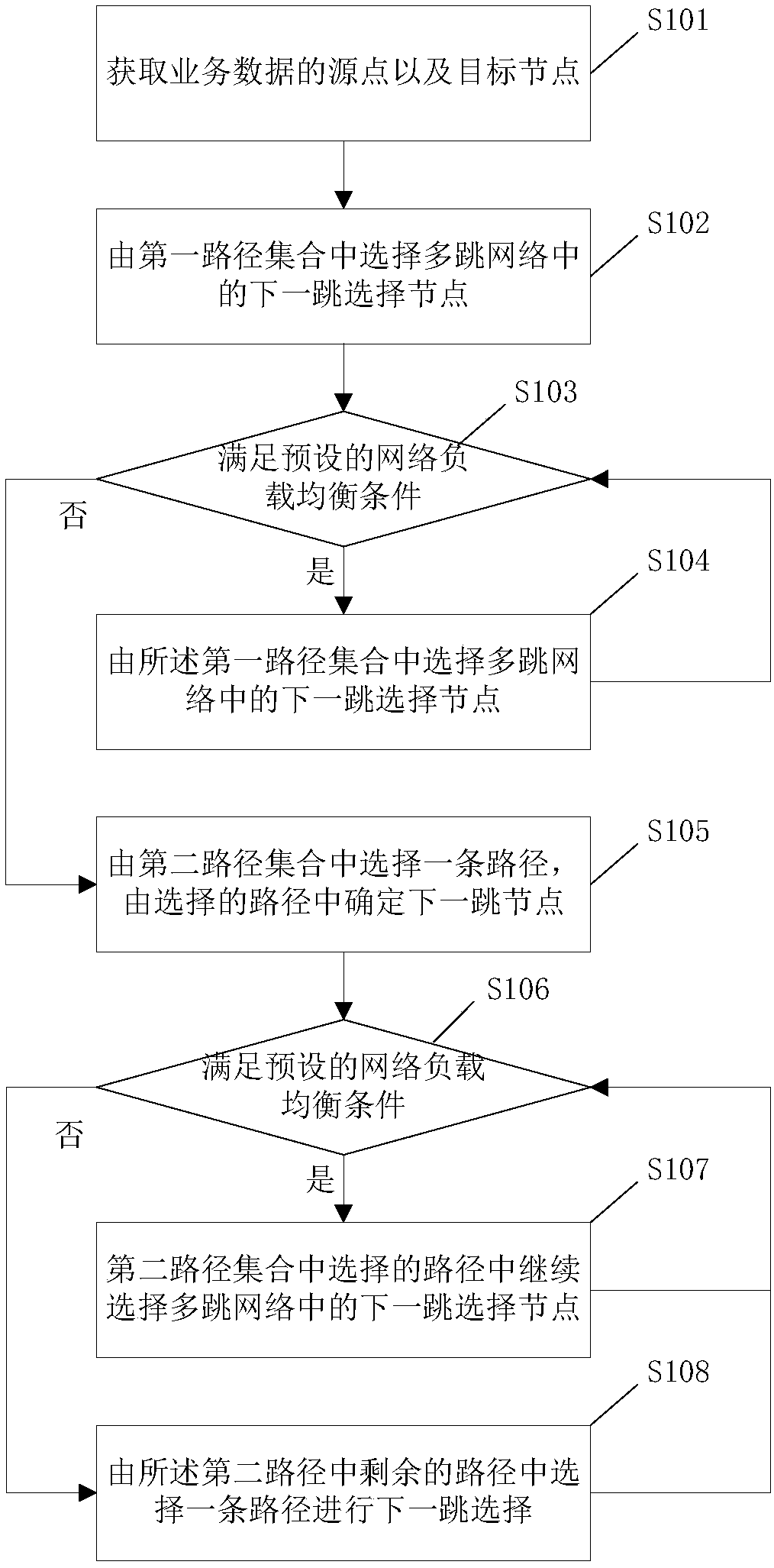
[0078] The purpose of the present invention is to study the wireless network path planning method, by minimizing the total energy consumption of the network, and simultaneously balancing the remaining energy of all nodes in the network, to prolong the life cycle of the network.

[0079] Through the research, it is found that the life cycle of the network is related to its energy consumption and load balancing degree, so the network energy consumption and ...


PUM


Abstract

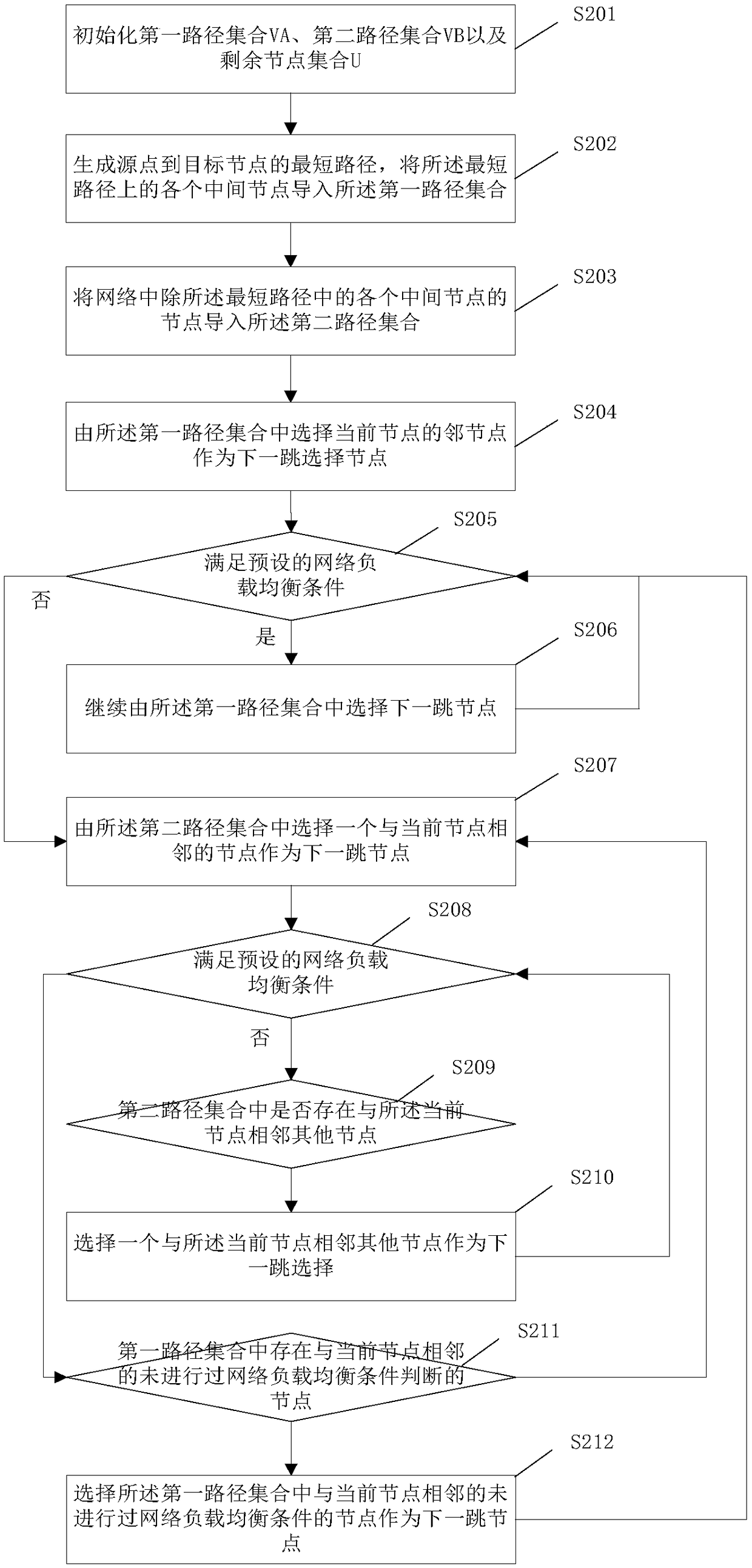
The invention provides a wireless network path planning method and device. The method comprises the following steps of judging whether a next-hop node meets a preset network load balancing condition or not when the next-hop node is selected; if yes, taking the node as the next hop node; and if no, selecting other paths for next-hop selection until the next-hop node is a target node. Service data is transmitted according to a determined path formed by the nodes meeting the network load balancing condition, so that the network load balance degree is improved, and the life cycle of a network is prolonged.

Description

technical field [0001] The invention relates to the technical field of data communication, in particular to a method and system for planning a wireless network path based on energy consumption. Background technique [0002] Wireless sensor networks can carry a variety of power communication services and play an important role in smart grids. However, sensor nodes are generally powered by batteries, which have the disadvantage of not being easy to replenish. Therefore, an important criterion for measuring wireless sensor networks is the life cycle. The life cycle of sensor nodes is related to the battery life of each node and the energy consumption required for data transmission and reception. In wireless sensor networks, because some nodes are in key positions in the network, many source nodes need to forward services through this key node when forwarding, causing the energy of key nodes to be exhausted rapidly, which in turn causes the load of the entire network to be unsa...

Claims


Application Information

Patent Timeline
IPC IPC(8): H04W28/08H04W40/10H04W40/20H04W52/02
CPCH04W28/08H04W40/10H04W40/20H04W52/0203Y02D30/70
Inventor 张喆李温静吴庆曾令康孟凡博栾敬钊叶跃骈冯笑刘玉民李帅张晓惠刘欢欢
Owner STATE GRID LIAONING ELECTRIC POWER RES INST
Learn More