Pneumatic tire, having working layers comprising monofilaments and a tire tread with incisions

A working layer, tire technology, applied in the direction of tire tread/tread pattern, reinforcement layer of pneumatic tires, tire parts, etc., can solve the problems of buckling, insufficient tire durability, etc.

Active Publication Date: 2018-06-08
MICHELIN & CO CIE GEN DES ESTAB MICHELIN
View PDF9 Cites 1 Cited by
  • Summary
  • Abstract
  • Description
  • Claims
  • Application Information

AI Technical Summary

Problems solved by technology

[0016] However, the use of such reinforcing elements has the disadvantage of causing problems of buckling under compression, so that the tire exhibits insufficient durability, as described in document EP2537686

Method used


Image

  • Pneumatic tire, having working layers comprising monofilaments and a tire tread with incisions
  • Pneumatic tire, having working layers comprising monofilaments and a tire tread with incisions
  • Pneumatic tire, having working layers comprising monofilaments and a tire tread with incisions

Examples


Embodiment Construction

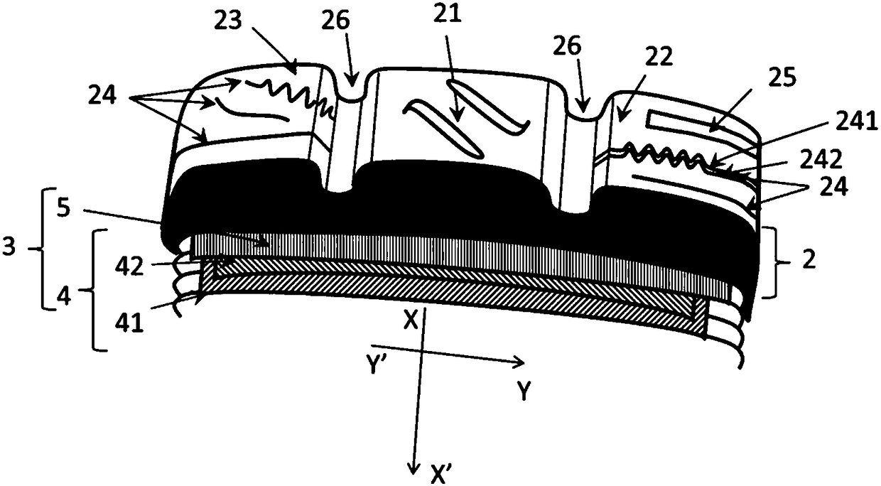
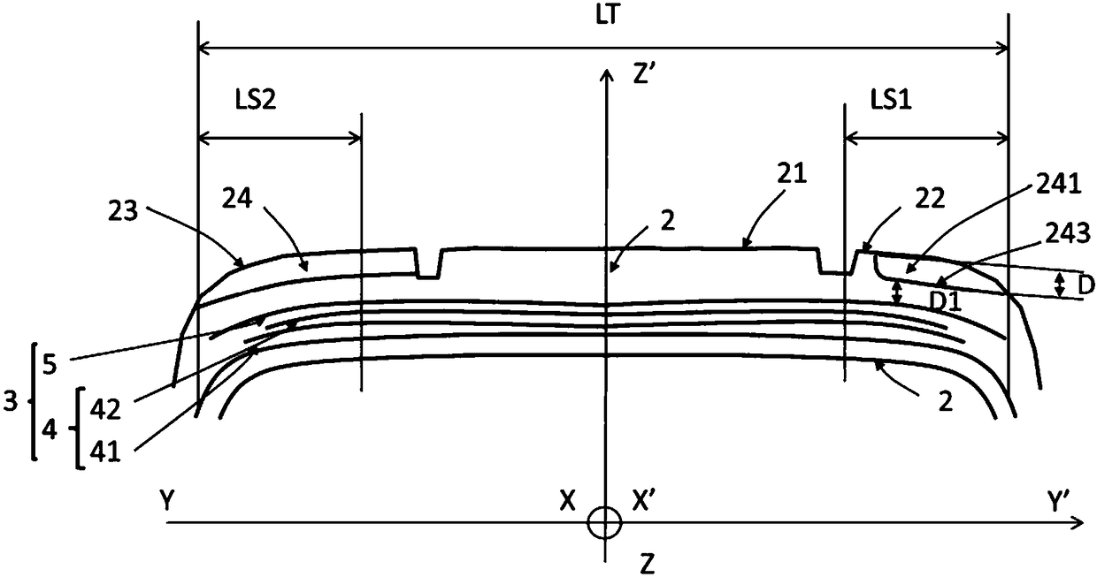
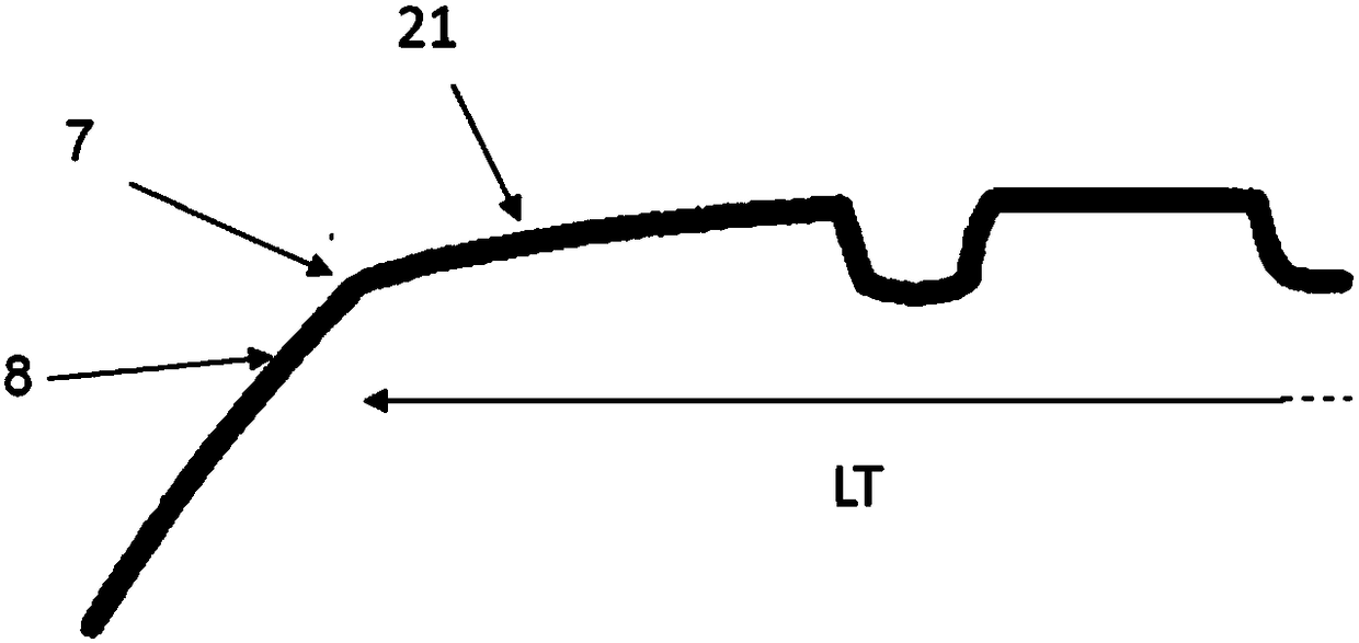
[0070] figure 1 The crown portion of the tire is shown. The tire comprises a tread 2 intended to come into contact with the ground via a tread surface 21 . In the axially outer portions 22 and 23 of the tread there are axially outer cuts comprising sipes 24 and grooves 25 . The tire further has a crown reinforcement 3 comprising a working reinforcement 4 comprising two working layers 41 and 42 and a hooping reinforcement 5 . figure 1 Further shown are simple and complex blind grooves, double blind grooves and cutouts axially leading to the outside or inside (i.e. with parallel side surfaces in the main direction of the cutout or in its depth direction or with zigzag or sinusoidal sections The cutout of the side surface), thereby preventing some relative movement of the two side surfaces.

[0071] figure 1 Only the axially outer grooves extending along the axial axis (YY') are shown in the axially outer portions 22 and 23 of the tread. In fact, the figure is only for re...


PUM

PropertyMeasurementUnit
distanceaaaaaaaaaa
distanceaaaaaaaaaa
diameteraaaaaaaaaa

Abstract

The objective of the invention is to increase the endurance of tires having 2 crossed working layers (41, 42), comprising parallel reinforcing elements which are at an angle of at least 20 degrees andno greater than 50 degrees to the circumferential direction (XX') of the pneumatic tire, said reinforcing elements being made of single metal wires or monofilaments having a cross-section of at least0.20 mm and no more than 0.5 mm. The pneumatic tire further comprises incisions (24) axially on the outside, which have a mean width W of no more than 1 mm and a depth D of at least 5 mm and which, in the circumferential direction (XX') are spaced apart from a circumferential pitch of at least 4 mm, and grooves (25) axially on the outside, which have a mean width W of at least 1 mm and a depth Dof no more than 5 mm.

Description

technical field [0001] The present invention relates to tires for passenger vehicles, and more particularly to the crown of said tires. [0002] Since the geometry of the tire exhibits rotational symmetry about the axis of rotation, the geometry of the tire is usually described in a meridian plane including the axis of rotation of the tire. For a given meridian plane, radial, axial and circumferential directions denote directions perpendicular to the axis of rotation of the tire, parallel to the axis of rotation of the tire and perpendicular to the meridian plane, respectively. [0003] Hereinafter, the expressions "radially inner" and "radially outer" mean "closer in the radial direction to the axis of rotation of the tire" and "farther in the radial direction from the axis of rotation of the tire", respectively. The expressions "axially located on the inside" and "axially located on the outside" mean "in the axial direction closer to the equatorial plane" and "in the axial ...

Claims


Application Information

Patent Timeline
Patent Type & Authority Applications(China)
IPC IPC(8): B60C11/12B60C9/22B60C9/00B60C11/03B60C9/20
CPCB60C2011/0367B60C2011/0362B60C2011/0358B60C11/1259B60C2011/0365B60C11/1272B60C9/22B60C11/12B60C9/0064B60C2009/2019B60C11/1263B60C9/0007B60C9/0042B60C9/1807B60C9/2009B60C11/04B60C11/1204B60C11/1236B60C2009/0085B60C2009/1828B60C2009/2016B60C2009/2077B60C2009/2083B60C2009/209B60C2011/1213B60C2011/1254B60C2011/129
Inventor A·博内特J-C·德罗贝尔-马聚尔J·莫雷尔-让
Owner MICHELIN & CO CIE GEN DES ESTAB MICHELIN
Why Eureka
Try Eureka