New-energy vehicle roof charging connecting device and working method thereof

A new energy vehicle, charging connection technology, applied in the direction of electric vehicle charging technology, charging stations, electric vehicles, etc., to achieve the effect of convenient use and expanding the range of movement

Inactive Publication Date: 2018-06-12
ZHEJIANG DIHENG IND CO LTD
View PDF6 Cites 7 Cited by
  • Summary
  • Abstract
  • Description
  • Claims
  • Application Information

AI Technical Summary

Problems solved by technology

This has requirements for parking technology, and many novice drivers cannot meet this requirement

Method used


Image

  • New-energy vehicle roof charging connecting device and working method thereof
  • New-energy vehicle roof charging connecting device and working method thereof
  • New-energy vehicle roof charging connecting device and working method thereof

Examples


no. 1 example

[0030] The charging connection device on the roof of a new energy vehicle in this embodiment includes a bracket assembly and a first moving assembly.

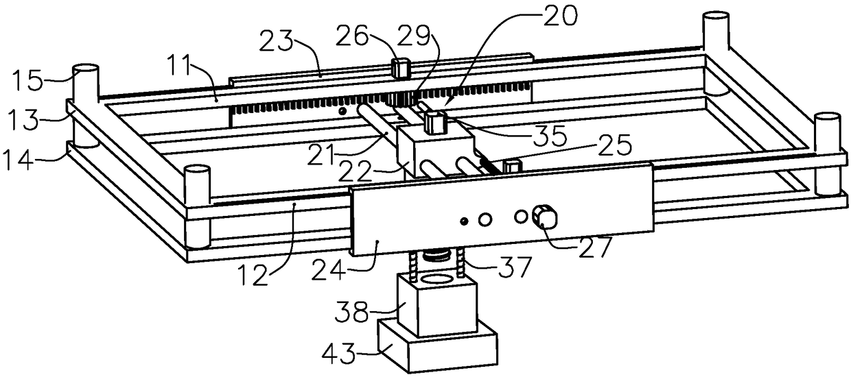
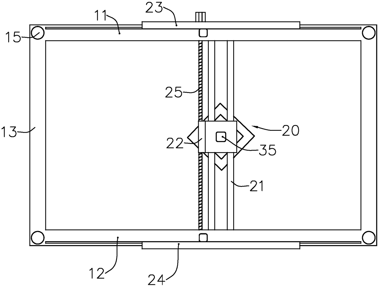
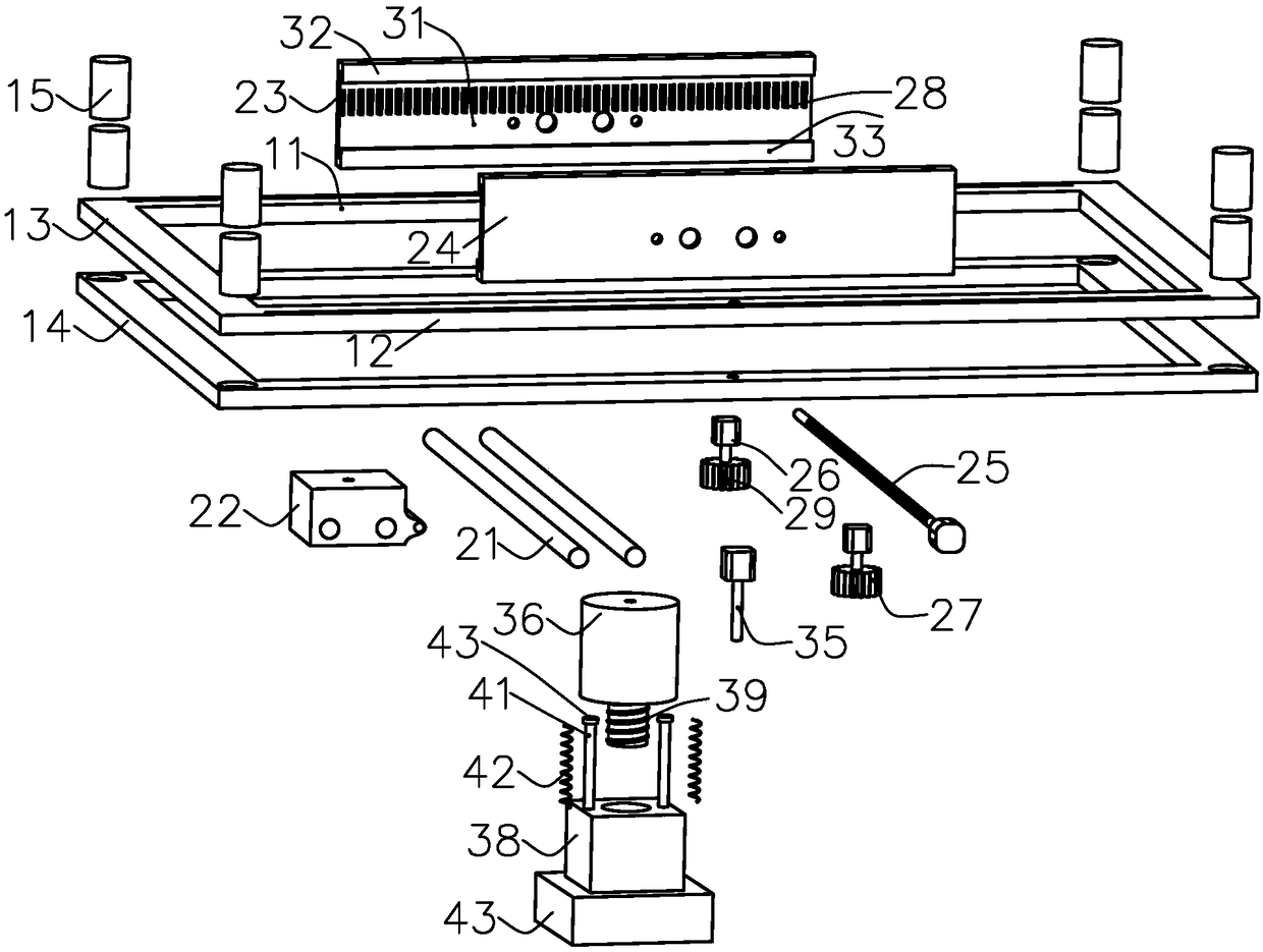
[0031] Such as Figure 1~6 As shown, the bracket assembly has a first rod body 11 and a second rod body 12 disposed opposite to each other. Preferably, the bracket assembly includes an upper rectangular frame 13 and a lower rectangular frame 14, and the upper rectangular frame 13 and the lower rectangular frame 14 are connected by a column bracket 15, and a distance is formed between the upper rectangular frame 13 and the lower rectangular frame 14. The upper rectangular frame 13 or the lower rectangular frame 14 includes a first rod body 11 and a second rod body 12 arranged in parallel.

[0032] Two ends of the first moving assembly 20 are respectively slidingly connected to the first rod body 11 and the second rod body 12 , and the first moving assembly 20 can move along the extending direction of the first rod body 11 . Sp...

no. 2 example

[0044] In this embodiment, a wired charging component is also provided at a position between the wireless charging box 43 and the lifting block 38 . The wired charging assembly includes a wired charging plug-in rod, a wired charging plug-in device, and a fourth motor. The wired charging plug-in rod is hinged on the lifting block 38. The fourth motor is connected to the wired charging plug-in rod through the transmission assembly, and the fourth motor The position of the wired charging plug-in pole can be changed to adjust the angle of the wired charging plug-in device, and finally the wired charging plug-in device can be matched with the charging interface on the roof of the car.


PUM


Abstract

The invention relates to a new-energy vehicle roof charging connecting device and a working method thereof. The new-energy vehicle roof charging connecting device comprises a bracket assembly and a first moving assembly, and the bracket assembly is provided with a first rod body and a second rod body which are arranged oppositely; the first moving assembly can move in the extension direction of the first rod body; and the lower end of a moving block is connected with a charging connecting structure, and the charging connecting structure can move in the vertical direction relative to the movingblock. The moving block can move freely in the two-dimensional direction of a horizontal plane, and the charging connecting structure can further move in the vertical direction, so that the moving range of the charging connecting structure is expanded greatly, a vehicle owner only needs to park a vehicle to the lower position of the charging connecting device without needing to park the vehicle to the excessively precise position, the charging connecting structure can be automatically matched to the charging position of a vehicle roof through position moving, and using is very convenient.

Description

technical field [0001] The invention relates to the field of battery charging, in particular to the field of charging the roof of a new energy vehicle. Background technique [0002] The existing electric vehicle charging is divided into two types, one is wired charging and the other is wireless charging. Among them, wired charging piles take up too much space, and can only charge two vehicles at most. Although wireless charging can charge multiple vehicles at the same time, it also takes up ground space because of the need for power supply piles, and vehicles must be aligned when parking in the parking lot. The quasi-ground wireless charging device will crush the ground device if you are not careful. This has a requirement for parking technology, and now many novice drivers cannot meet this requirement. Contents of the invention [0003] The main purpose of the present invention is to provide a new energy vehicle charging device connected from the roof, and the device is...

Claims


Application Information

Patent Timeline
Patent Type & Authority Applications(China)
IPC IPC(8): B60L11/18
CPCB60L53/14B60L53/35Y02T10/70Y02T10/7072Y02T90/12Y02T90/14
Inventor 魏亮
Owner ZHEJIANG DIHENG IND CO LTD
Why Eureka
Try Eureka