

Bridge erecting machine
A bridge erecting machine and front outrigger technology, applied in the erection/assembly of bridges, bridges, bridge construction, etc., can solve problems such as structural design defects, poor stability and reliability, affecting normal use, etc., to facilitate bridge erection, stable and reliable. High and extended range of motion
- Summary
- Abstract
- Description
- Claims
- Application Information
AI Technical Summary
Problems solved by technology
Method used
Image

Examples
Embodiment Construction
[0015] The technical solutions of the present invention will be further described below in conjunction with the accompanying drawings and through specific implementation methods.
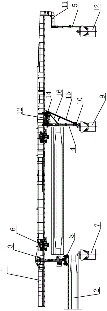
[0016] see figure 1 as shown, figure 1 It is a structural schematic diagram of the bridge erecting machine provided in Embodiment 1 of the present invention.
[0017] In this embodiment, a bridge erecting machine includes a main girder 1, a cart track 2, a rear outrigger 3, a front outrigger 4, an auxiliary outrigger 5, and two hoisting mechanisms 6 for hoisting beams, The two lifting mechanisms 6 are movably arranged on the main beam 1, the main beam 1 is formed by splicing several sections through fixing pins, and one end of the cart track 2 is arranged on the first support pile 7 , the rear section of the main beam 1 is provided with a rear outrigger 3, the rear outrigger 3 is arranged on the cart track 2, and the rear outrigger 3 is provided with a jacking and lateral movement support assembly...
PUM
 Abstract
Description
Claims
Application Information