
Rod part labeling device

A technology for label stickers and parts, applied in the field of labeling equipment, can solve the problems of poor label sticking, affecting the appearance of products, reducing product qualification rate, etc., to achieve the effect of convenient and quick installation, firm label sticking, and reducing diversity

Inactive Publication Date: 2018-06-12
新昌县小毅家电子商务有限公司
View PDF0 Cites 2 Cited by
  • Summary
  • Abstract
  • Description
  • Claims
  • Application Information

AI Technical Summary

Problems solved by technology

[0002] Most of the products on the market now need to set logos to indicate the model specifications of the products, or to affix the manufacturer's logo, which is used to easily distinguish different manufacturers of similar products. Labeling machines are commonly used labeling equipment. At present, the types of labeling machines produced in my country are gradually increasing, and the technical level has also been greatly improved. It has changed from the backward situation of manual and semi-automatic labeling to automatic high-speed labeling machines. The production volume of batteries is large, and all need labeling. Setting, it is necessary to indicate the capacity and brand of the battery on the label of the battery, but due to the small size of the battery, it is necessary to ensure the accuracy of the blanking when labeling, so the battery blanking procedure It is very important. At the same time, it is necessary to ensure that the film tension on the label is stable when labeling. At present, the labeling device is directly transported to the next link after labeling the layer, and no further pressing is performed, resulting in some labels being not firmly attached. Affect the appearance of the product and reduce the qualified rate of the product

Method used


Image

  • Rod part labeling device
  • Rod part labeling device
  • Rod part labeling device

Examples


Embodiment Construction

[0027] It should be noted that, in the case of no conflict, the embodiments of the present invention and the features in the embodiments can be combined with each other.

[0028] In describing the present invention, it should be understood that the terms "center", "longitudinal", "transverse", "upper", "lower", "front", "rear", "left", "right", " The orientations or positional relationships indicated by "vertical", "horizontal", "top", "bottom", "inner" and "outer" are based on the orientations or positional relationships shown in the drawings, and are only for the convenience of describing the present invention and Simplified descriptions, rather than indicating or implying that the device or element referred to must have a particular orientation, be constructed and operate in a particular orientation, and thus should not be construed as limiting the invention. In addition, the terms "first", "second", etc. are used for descriptive purposes only, and should not be understood ...


PUM


Abstract

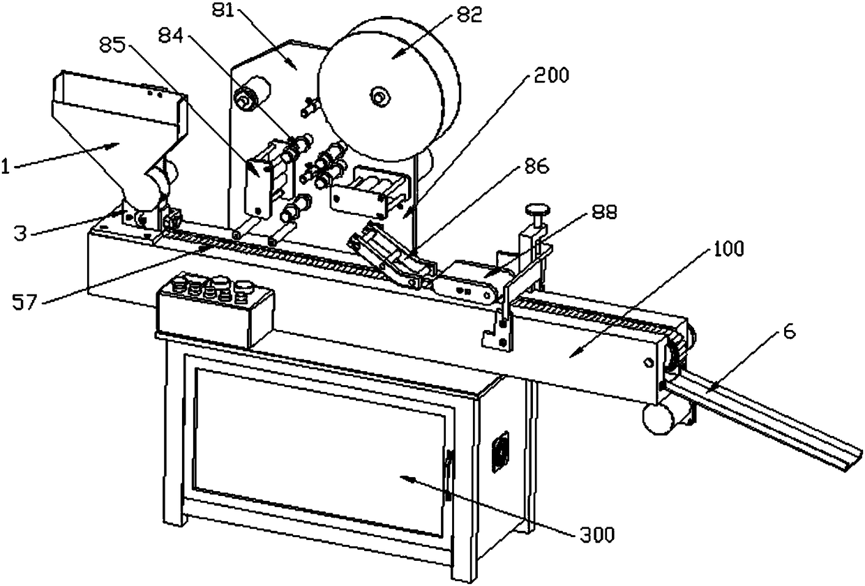
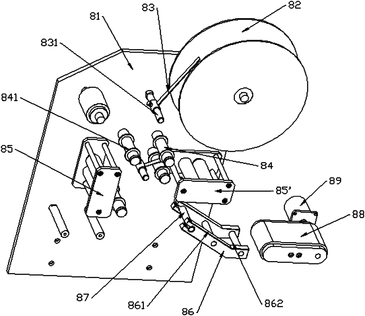
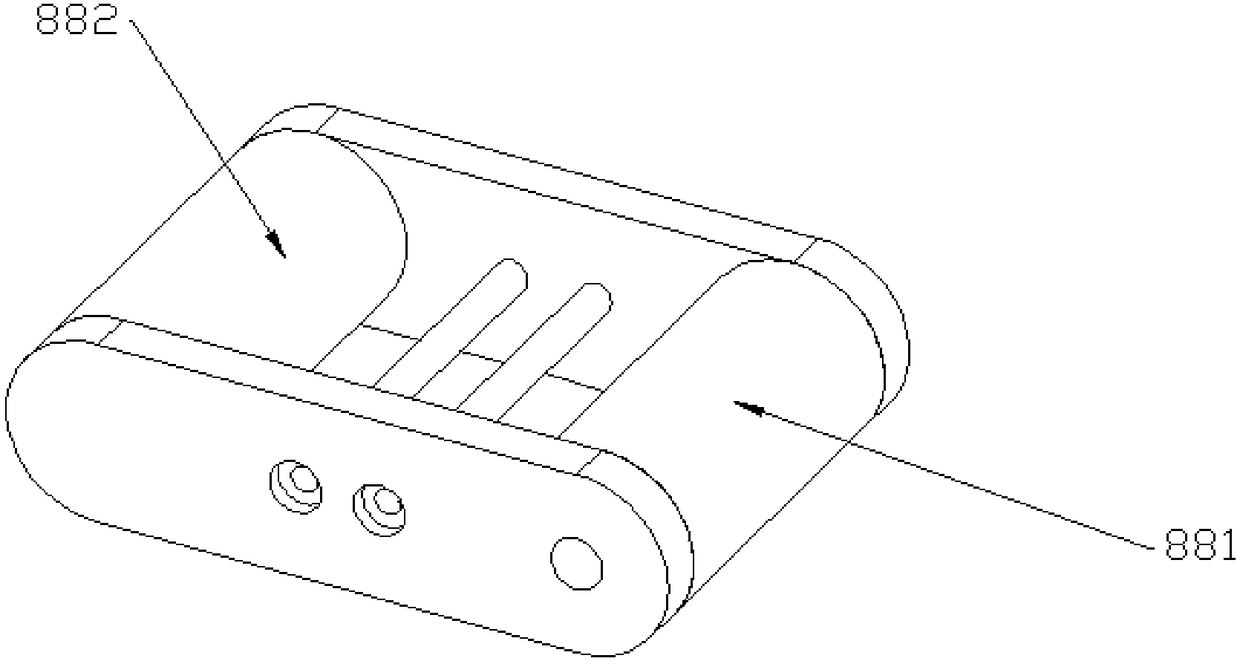
The invention provides a rod part labeling device and belongs to the field of labeling equipment. The rod part labeling device comprises a feeding assembly, a press-covering assembly and a working table. The feeding assembly is arranged above the working table. The press-covering assembly is arranged on one side of the working table. The feeding assembly comprises a discharge chute, a discharge wheel, a guide block and a conveying assembly. The width of the discharge chute is greater than the length of one battery and less than the length of the two batteries. The discharge chute comprises a feed area located at the upper end and a transition area located at the lower end. The transition area is circular. The discharge wheel is arranged in the transition area and is rotatably connected tothe transition area. A plurality of locating grooves are uniformly formed in the discharge wheel. The axes of the locating grooves are perpendicular to the width direction of the discharge chute. Theguide block is arranged at the lower end of the transition area. A speed reduction groove communicating with the transition area is formed in the guide block. A transmission assembly arranged horizontally is arranged at the lower end of the speed reduction groove. The longitudinal center line of the transmission assembly is parallel to the center lines of the locating grooves. The rod part labeling device is accurate in feeding, capable of achieving rapid labeling of a label on the outer surface of a rod part and high in efficiency.

Description

technical field [0001] The invention belongs to the field of labeling equipment and relates to a label sticking device for rod-shaped parts. Background technique [0002] Now most of the products on the market need to set logos to indicate the model specifications of the products, or to affix the manufacturer's logo, which is used to easily distinguish different manufacturers of similar products. Labeling machines are commonly used labeling equipment. At present, the types of labeling machines produced in my country are gradually increasing, and the technical level has also been greatly improved. It has shifted from the backward situation of manual and semi-automatic labeling to automatic high-speed labeling machines. The production volume of batteries is large, and all need labeling. Setting, it is necessary to indicate the capacity and brand of the battery on the label of the battery, but due to the small size of the battery, it is necessary to ensure the accuracy of the bla...

Claims


Application Information

Patent Timeline
IPC IPC(8): B65C9/02B65C9/18B65C9/36
CPCB65C9/02B65C9/18B65C9/36
Inventor 陈勇吉
Owner 新昌县小毅家电子商务有限公司
Learn More