
Thrust bearing and holder used for thrust bearing

A technology for thrust bearings and cages, applied in the field of cages, can solve problems such as reverse installation of thrust needle roller bearing cages, and achieve the effect of reversing cages

Active Publication Date: 2018-06-12
SCHAEFFLER TECH AG & CO KG
View PDF6 Cites 2 Cited by
  • Summary
  • Abstract
  • Description
  • Claims
  • Application Information

AI Technical Summary

Problems solved by technology

[0004] The problem solved by the invention is that the existing thrust needle roller bearings have the problem of reverse mounting of the cage

Method used


Image

  • Thrust bearing and holder used for thrust bearing
  • Thrust bearing and holder used for thrust bearing
  • Thrust bearing and holder used for thrust bearing

Examples


no. 1 example

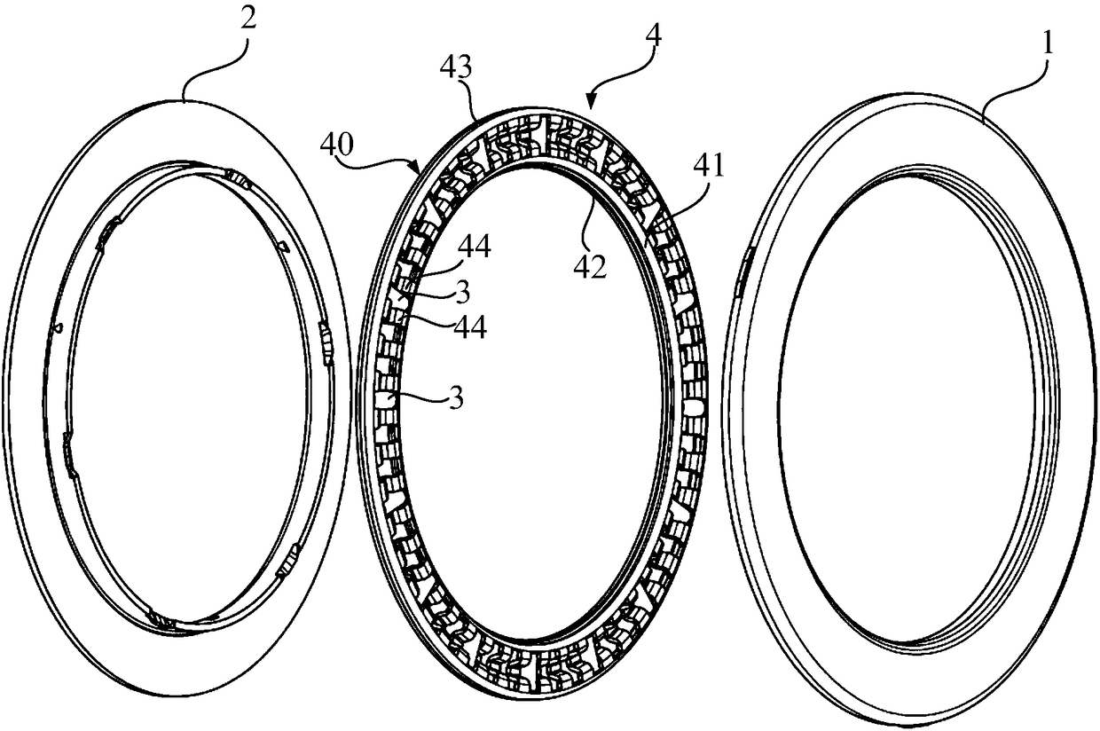
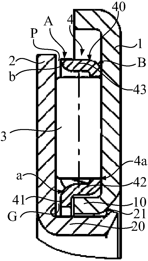
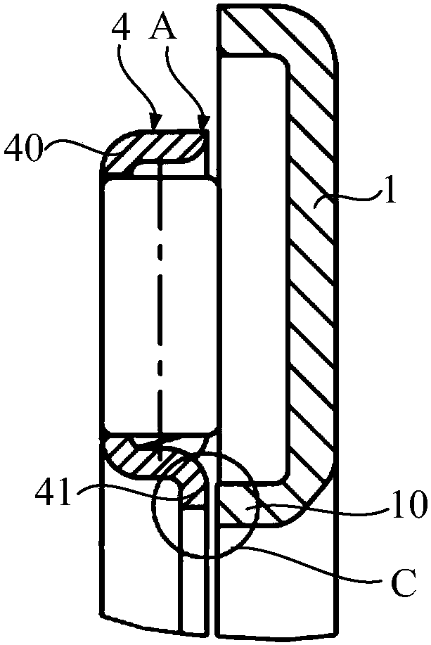
[0028] refer to figure 1 and figure 2 , the thrust bearing may include: a first washer 1 and a second washer 2 arranged axially and a number of rolling elements 3 arranged between the first washer 1 and the second washer 2, the first washer 1 has a direction toward the second washer 2 The axially protruding first protruding ring 10 and the rolling elements 3 are arranged along the circumferential direction of the thrust bearing, and the first washer 1 and the second washer 2 can realize relative rotation through the rolling elements 3 . The thrust bearing may also comprise a cage 4 in which the rolling elements 3 are defined.

[0029] The cage 4 includes: a body frame 40, which has an inner peripheral surface and an outer peripheral surface, and the two axial ends are respectively a first end A and a second end B; a radial inner protrusion 41 is connected to the first end A, and The body frame 40 is radially inwardly higher than the inner peripheral surface of the body fram...

no. 2 example

[0045] refer to Figure 5 , The cage 5 in this technical solution includes: a radially outer protrusion 51 connected to the first end A′, and the outer protrusion 51 can be higher than the outer peripheral surface of the body frame 50 radially outwards along the body frame 50 . Therefore, when the cage 5 is correctly assembled in the thrust bearing, the first washer 6 also has a third collar 60 surrounding the body frame 50, and the outer protrusion 51 is at least partially axially opposite to the third collar 60, so that the body frame 50 Can be accommodated between the first collar 10 and the third collar 60 .

[0046] During assembly, if the retainer 5 is reversed, the outer protrusion 51 will interfere with the third protruding ring 60 , so that the retainer 5 cannot be installed on the first washer 6 . Therefore, the retainer 5 of the present technical solution can avoid the problem of reverse installation of the retainer 5 .

[0047] Referring to the shape of the inner...


PUM


Abstract

Disclosed are a thrust bearing and a holder used for the thrust bearing. The holder comprises a body frame, the body frame is provided with an inner circumferential surface and an outer circumferential surface, and one of the two axial ends of the body frame is a first end; the holder further comprises a radial inner protruding part and / or a radial outer protruding part, wherein the radial inner protruding part is connected to the first end and higher than the inner circumferential surface inwards in the radial direction of the body frame; and the radial outer protruding part is connected to the first end and higher than the outer circumferential surface outwards in the radial direction of the body frame. According to the technical scheme, the holder can be used for solving the problem that a holder is mounted reversely in the prior art, accurate assembling of the holder is achieved, it is ensured that the thrust bearing is effectively lubricated, and the risk of rotating clamping stagnation of the bearing is reduced.

Description

technical field [0001] The invention relates to the technical field of bearings, in particular to a thrust bearing and a cage used for the thrust bearing. Background technique [0002] Thrust needle roller bearings mainly bear axial loads. An existing thrust needle roller bearing includes: a first washer and a second washer arranged axially, the first washer has a first protrusion protruding axially toward the second washer ring, the second washer has a second protruding ring axially protruding, the first protruding ring is sleeved outside the second protruding ring; A number of needle rollers in the frame. Along the axial direction of the bearing, the outer peripheral surface of the needle roller is in contact with the first washer and the second washer, and can roll around its central axis along the first washer and the second washer when the first washer and the second washer rotate relative to each other. During application, the second collar may be fixedly fitted over...

Claims


Application Information

Patent Timeline
Patent Type & Authority Applications(China)
IPC IPC(8): F16C19/10F16C19/30F16C33/38F16C33/46F16C33/66
CPCF16C19/10F16C19/30F16C33/38F16C33/46F16C33/6603
Inventor 娄兆海
Owner SCHAEFFLER TECH AG & CO KG
Learn More