Automobile transmission shaft

A transmission shaft and transmission shaft tube technology, applied in the direction of couplings, elastic couplings, mechanical equipment, etc., can solve the problems of reducing efficiency, impact and noise, sliding resistance, etc., to simplify the complexity of the structure and ensure reliable transmission , Improve the effect of transmission efficiency

Active Publication Date: 2018-06-12
ANHUI JIANGHUAI AUTOMOBILE GRP CORP LTD
View PDF3 Cites 0 Cited by
  • Summary
  • Abstract
  • Description
  • Claims
  • Application Information

AI Technical Summary

Problems solved by technology

[0004] This structure has the following disadvantages after analysis and use: First, the cross-shaft universal joint is a non-uniform transmission universal joint, which produces speed fluctuations during the rotation process, and there is a backlash between teeth due to the sliding spline c

Method used


Image

  • Automobile transmission shaft
  • Automobile transmission shaft
  • Automobile transmission shaft

Examples


Embodiment Construction

[0040] Embodiments of the present invention are described in detail below, and examples of the embodiments are shown in the drawings, wherein the same or similar reference numerals denote the same or similar elements or elements having the same or similar functions throughout. The embodiments described below by referring to the figures are exemplary only for explaining the present invention and should not be construed as limiting the present invention.

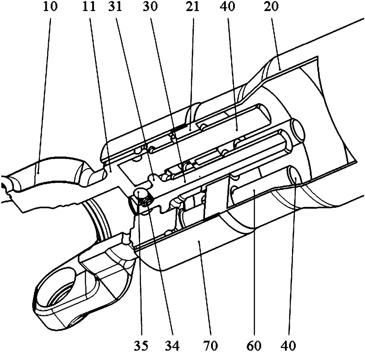
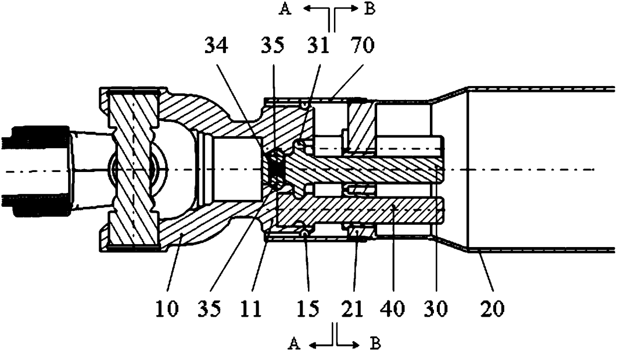
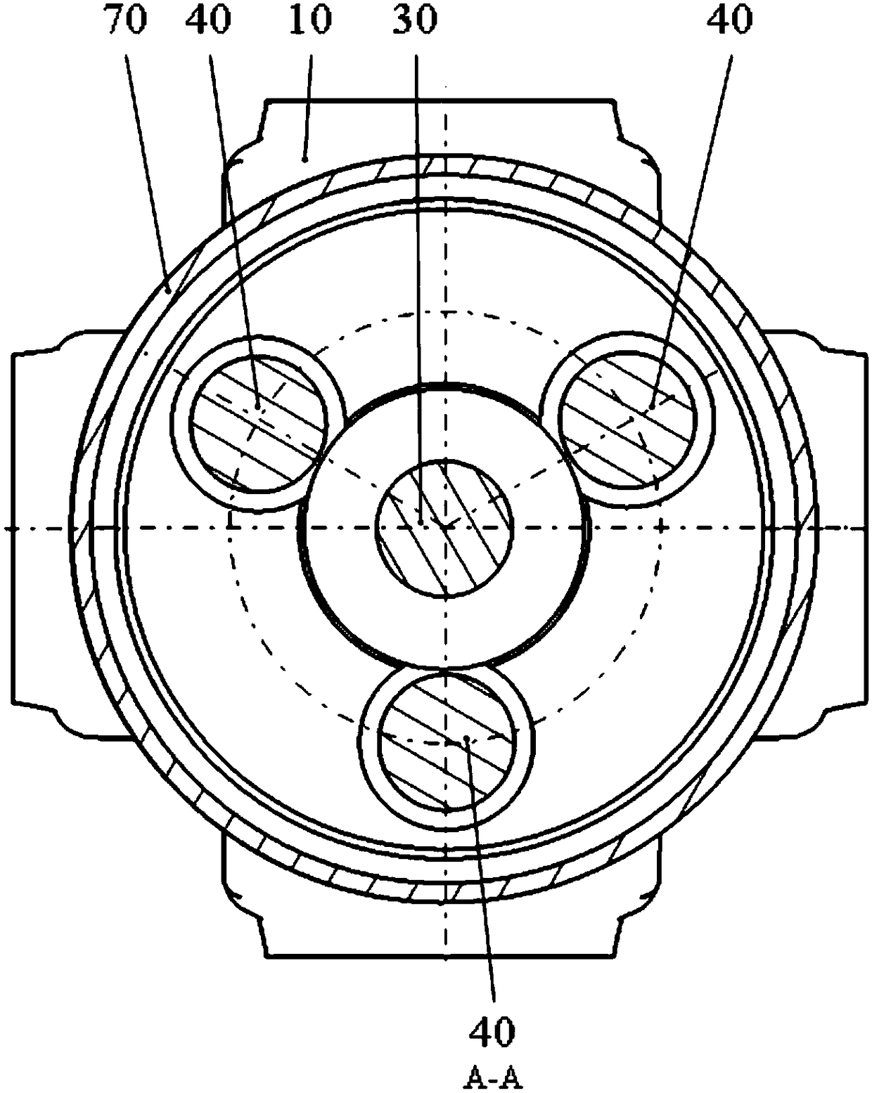
[0041] Such as Figure 1 to Figure 8 As shown, the automobile transmission shaft provided by the embodiment of the present invention includes a universal joint yoke 10 , a transmission shaft tube 20 , a central shaft 30 and an eccentric shaft 40 .

[0042] Wherein, one end of the universal joint yoke 10 is provided with a first flange 11, and the first flange 11 penetrates a first central hole 12 and a first eccentric hole 13 in the axial direction; In the middle part, the first eccentric hole 13 is distributed on the circumf...


PUM


Abstract

The invention discloses an automobile transmission shaft. The automobile transmission shaft comprises a universal joint fork, a transmission shaft pipe, a center shaft and eccentric shafts, wherein one end of the universal joint fork is provided with a first flange, a first center hole is formed in the first flange, and the side wall of the first center hole is provided with a semi-circular ring groove; and the center shaft can move in the axial direction of the transmission shaft pipe, a penetrating hole is formed in the center shaft in the axial direction, a spring and two steel balls are installed in the penetrating hole, the two steel balls are located at the two ends of the penetrating hole, the two ends of the spring abut against the two steel balls correspondingly, and the parts, stretching out of the penetrating hole, of the two steel balls are embedded in the semi-circular ring groove. Due to the fact that the center shaft and the eccentric shafts can move in the transmissionshaft pipe, the requirements for relative position change between a speed changer and the input end of a driving shaft, the eccentric shafts can transmit output power of the speed changer to the inputshaft end of the driving shaft. Reliable torque transmitting is ensured, in addition, by adopting the mode that the center shaft is fixed through cooperation of the steel balls and the spring, the structure complexity is reduced, and the transmission efficiency is improved.

Description

technical field [0001] The invention relates to the technical field of automobiles, in particular to an automobile transmission shaft. Background technique [0002] The automobile transmission shaft is an important part connecting the transmission and the drive axle in the automobile transmission system. It is connected between the transmission of the power unit and the input shaft of the drive shaft, and is mainly used to transmit the output power of the transmission to the input shaft of the drive shaft. . According to the impact from the road surface or the operating state of the vehicle, the relative position between the transmission and the input shaft of the drive shaft will change. Therefore, the transmission shaft is required to be able to transmit torque, and the length can be expanded to meet the needs of the transmission and the drive shaft. Relative positional change requirements between input shafts. [0003] In the prior art, the transmission shaft of automob...

Claims


Application Information

Patent Timeline
IPC IPC(8): F16D3/26
CPCF16D3/26
Inventor 孙光仙陈正江姜超左印波
Owner ANHUI JIANGHUAI AUTOMOBILE GRP CORP LTD
Why Eureka
Try Eureka